owners manuaL C D P L A Y ERS EN G L I S H D EU T S C H F RAN Ç A I S I T A L I AN 0
Cont ent s SAFETY INSTRUCTIONS In order to comply with current European safety regulations it is essential that the Naim loudspeaker connectors supplied with amplifiers and loudspeakers are used. Do not under any circumstances allow anyone to modify your Naim equipment without first checking with the factory, your retailer, or your distributor. Unauthorised modifications will invalidate your guarantee.
I ntrod u c tio n Naim Audio products are conceived with performance as the top priority. Careful installation will help ensure that their full potential is achieved. This manual covers the CD 555, CDS3, CDX2, CD5 XS and CD5i CD players and their associated or upgrade power supplies. It begins with some general installation notes and statutory safety warnings. Product specific information begins in Section 4.
I ntrod u c tio n 3 Gen er al Instal l a ti o n Naim equipment is designed to offer the finest In some circumstances, depending on where you live performance possible avoiding compromise and the earthing arrangements in your home, you may wherever practical. This can lead to circumstances experience radio frequency interference. Controls on that may be unfamiliar.
CD 555 4 CD 5 5 5 In t ro d ucti o n a nd Instal l a ti on The CD 555 CD Player can only be operated from a Naim CD 555PS Power Supply. Connection of the power supply is illustrated in Section 5.2. CD player control and operation is described in Sections 19, 20 and 21. The CD 555 should be installed on a dedicated equipment stand intended for the purpose. To improve sound quality the player has hard metallic feet which may blemish any delicate surface on which it is placed.
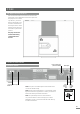
CD 555 5 CD 5 5 5 Connecti o ns 5. 1 Rear P anel Comms interface RC5 input DIN output RCA phono outputs left (ch1) and right (ch2) Note: RCA phono and DIN output sockets should not be CD 555PS Power Supply inputs connected simultaneously. Note: The RC5 Input is intended to accept external control CD 555 DIN Output signals for multi-room applications. Contact your dealer or Naim Audio directly for further information.
CD 555 6 CD 5 5 5 In Use 6. 1 D isc Loading 6 . 3 P l a y er Door R es et a n d C a l i b r a t i on If at any time the player door fails to open or close correctly, or the top panel door button flashes, the door To open the transport door press the player door button may need re-setting and calibrating. The procedures are or the handset open key. To load a disc place it on the as follows. platter followed by the magnetic puck. Do not use a puck from any other Naim CD player.
C D S3 7 CDS3 In t r oducti o n a nd Instal l a ti on The CDS3 CD Player can only be operated from a Naim XPS or CD 555PS power supply. Connection of the XPS Power Supply is illustrated in Diagram 8.2. CD player control and operation is described in Sections 19, 20 and 21. The CDS3 should be installed on a dedicated equipment stand intended for the purpose. To improve sound quality the player has hard metallic feet which may blemish any delicate surface on which it is placed.
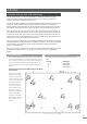
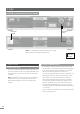
C D S3 7. 2 Upper Transit S c re ws Two transit screws must be removed from beneath the transport lid of the CDS3 before use and be replaced if the player is to be carried any distance, packed or shipped. The transit screw locations are illustrated in the diagram below. CDS3 transit screws must not be used with any other Naim product. The player must not be inverted either during or after transit screw removal. 8 CDS3 Con necti o ns Power supply input (XPS or CD 555PS) 8.
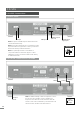
C D S3 8.2 CDS3 Connected to XPS Power Supply CD Burndy Cable Mains input and fuse Note: If a CD 555PS Power Supply is used to power a CDS3 player use only power supply output Socket 1. Cable direction marker 9 CDS3 In Use 9. 1 D isc Loading 9 .
CDX2 1 0 CDX2 In t rod ucti o n a nd Instal l a ti on The CDX2 CD Player can be operated either from its internal power supply or, for improved performance, from an external Naim CD 555PS or XPS Power Supply. Connection of the XPS Power Supply is illustrated in Diagram 11.2. CD player control and operation is described in Sections 19, 20 and 21. The CDX2 should be installed on a dedicated equipment stand intended for the purpose.
CDX2 11.2 CDX2 Connected to XPS Power Supply Note: If a CD 555PS Power Supply is used to power a CD Burndy Cable CDX2 player use only power supply output Socket 1. Mains input and fuse Note: When used with an external power supply the CDX2 player must be disconnected from the mains. Disconnect the player from the mains before connecting the power supply. 1 2 CDX2 In Use 12.1 Signal O utput S e le c tio n Cable direction marker 1 2 .
CD5 XS 1 3 CD5 XS Intro d ucti o n a nd Insta l l a ti on The CD5 XS CD Player can be operated either from its internal power supply only or, for improved performance, with an additional external Naim Flatcap or Hi-Cap power supply. Connection of the power supply is illustrated in Diagram 14.2. CD player control and operation is described in Sections 19, 20 and 21. The CD5 XS should be installed on a dedicated equipment stand intended for the purpose.
CD5 XS 14.2 CD5 XS Connected to FlatCap XS Power Supply Power switch Mains input and fuse Power switch Mains input and fuse Note: Both the FlatCap XS and CD5 XS must be connected to a mains supply and switched on. 1 5 CD5 XS In Use 15.1 Signal O utput S e le c tio n Cable direction marker 1 5 .
CD5i 1 6 CD5i I n t r od ucti o n a nd Instal l a ti on The CD5i should be installed on a dedicated equipment stand intended for the purpose. Do not stand the player directly on top of another item of Naim Audio equipment. Care should be taken to ensure that the player is level. A transit screw on the underside of the CD5i case should be removed before use and must be replaced if the unit is to be re-packed and shipped. This transit screw must not be used in any other Naim product.
C D Pla y er C o ntro l a nd Operat i on 1 9 CD P lay er Contro l a nd Opera ti on The operation and control of all Naim CD players is based on a common user interface. This section of the manual describes the user interface, drawing attention to differences between players where they occur. The CD player control buttons are duplicated on the remote control handset which may also provide some extra functions. The handset also provides CD programming facilities. See Sections 20 and 21 for more information.
R- c om R emo te H a nds et 2 0 R-com Remo te H and set The R-com remote handset is supplied with the NAC 552 and CD555 and can be purchased as an accessory. It offers quick and intuitive control of the most often used functions of CD players, preamplifiers, integrated amplifiers and tuners. To fit batteries, remove the bottom end cover using the tool provided and insert the batteries into the body taking care with their orientation. Replace the end cover.
N A R C O M 4 H a ndset 2 1 NAR COM 4 H a nd set The NARCOM 4 is a multi-functional remote control handset designed to be used with Naim Audio CD players, integrated amplifiers, preamplifiers, preset tuners and subwoofers. To fit batteries, remove the battery cover and insert the batteries into the body taking care with their orientation. Replace the battery cover. 21.1 Using NAR C OM Operation of the NARCOM handset is based around three types of keys: System Component Keys, Global Keys and Soft Keys.
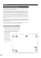
Pu c k I d entif ic a tio n 2 2 P u ck Identi fi c a ti o n Two different pucks are used to clamp CDs in the players covered by this manual (CD 555, CDS3, CDX2, CD5 XS and CD5i). Only the appropriate puck will work correctly in each player. The two pucks are illustrated below and their player applications listed.