
manual


E3
NAT05 XS Installation
4 NAT05 XS Installation
The NAT05 XS should be installed on a dedicated equipment stand intended for the
purpose. Do not stand it directly on top of another item of equipment. It should be
installed in its final location before connecting cables or switching on. Ensure also that the
system volume is turned down before switching on.
A number of power supply upgrade options are possible for the NAT05 XS. A diagram
illustrating the connection of one of these is shown in Section 7. Contact your local retailer
or distributor for advice if necessary on power supply connection.
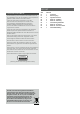
4.1 Aerial Requirements
The NAT05 XS aerial input socket must be connected via
75Ω low-loss coaxial cable to a suitable aerial.
Ideally the aerial should be mounted on the roof, clear
of obstructions and as high as possible. Use of an aerial
preamplifier may disturb the muting operation of the tuner
and may cause cross-modulation problems (interference
from an adjacent strong radio broadcast). Such
preamplifiers should only be used as a last resort.
Radio broadcasts are usually transmitted from different
sites even though the target areas of the services may be
similar. This means that unless the transmitters are in almost
the same direction looking from your house, an aerial
aligned on one transmitter will give less than optimum
performance on the other. In these circumstances you
should fit an aerial rotator, or a less directional aerial if
appropriate. The more sensitive and directional the aerial
you use, the worse will be the reception in directions other
than the one towards which the aerial is pointing. If you
are particularly interested in receiving a wide range of VHF
transmissions an aerial rotator is a necessity. Your retailer
will be familiar with local conditions and will be able to
advise you on which stations you can expect to receive
satisfactorily.
4.2 Audio Outputs
The NAT05 XS is fitted with both DIN and RCA-phono output
sockets. Use of the DIN option is preferred, however, if the
RCA-phono option is to be used it must be selected once
the NAT05 XS is switched on. Section 5.2 describes output
socket selection.
4.3 Power Supply Upgrades
The NAT05 XS can be upgraded through the addition of
an external FlatCap or Hi-Cap power supply. The external
supply works with the internal power supply of the NAT05 XS
to offer both a greater number of separate supplies and
more sophisticated voltage regulation.
The upgrade power supply is connected to the NAT05 XS
via a 240° five-pin DIN cable. Ensure that both the power
supply and NAT05 XS are switched off when making
connections. Remove the link plug and connect the supply
cable ensuring that the connectors are securely attached.
From their respective power switches, switch on the power
supply followed by the NAT05 XS. Diagram 7.2 illustrates the
connection of an external power supply.