WANGAN MIDNIGHT OPERATORS MANUAL IT IS THE RESPONSIBILITY OF THE OPERATOR TO MAINTAIN CUSTOMER SAFETY AT ALL TIMES, AND IT IS IMPERATIVE THAT THE DETAILS SET OUT IN THIS MANUAL ARE FOLLOWED PRECISELY Part No.
Contents OPERATORS MANUAL .............................................................................................................................. 1 GENERAL SAFETY CONSIDERATIONS .................................................................................................... 4 ALLGEMEINE SICHERHEITSHINWEISE ................................................................................................... 6 GENERELLE SIKKERHEDSOVERVEJELSER ..........................................................
7. INITIALIZATION .................................................................................................................................... 59 8. MAINTENANCE ................................................................................................................................... 8-1 Error Messages ......................................................................................................................... 8-2 Replacing the DVD-Rom Drive ......................................
No part of this publication may be reproduced by any mechanical, photographic or electronic process, or in the form of phonographic recording, nor may it be stored in a retrieval system, transmitted or otherwise copied for private use, without permission from NAMCO EUROPE LIMITED. While the information contained in this manual is given in good faith and was accurate at the time of printing, NAMCO EUROPE LIMITED reserve the right to make changes and alterations without notice.
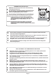
NOTES ON INSTALLATION 30cm or more Play zone 50cm or more In order to prevent possible electric shocks, be sure that the equipment is connected to the mains with a securely connected earthed plug. 2m 20cm or more 30cm or more 2m 20cm or more i NEVER turn the power to the machine ON until installation has been completed. In order to avoid damage to the equipment due to mis-operation, ensure that the voltage of the mains supply is 230volts AC.
D Dieses Dokument darf in keiner Weise vervielfältigt werden. Jegliche Tonaufnahmen sowie die Speicherung auf Datenträger (Suchsysteme), die Weitergabe oder sonstiges Kopieren für den gewerblichen und privaten Gebrauch sind untersagt und bedürfen der vorherigen Genehmigung durch NAMCO EUROPE LIMITED. Die informationen in diesem Handbuch entsprechen den Tatsachen bei Drucklegung. NAMCO EUROPE LIMITED behält sich jedoch das Recht zu Änderungen ohne vorherige Bekanntgabe vor.
HINWEISE ZUR AUFSTELLUNG Zur Vermeidung von Beschädigungen durch Fehlbetrieb am Gerät sicherstellen, daß die Netzspannung 230 Volt beträgt. Hinweis: Ist das Gerät für einen Aufstellplatz mit glattem Fußboden bestimmt, müssen die Standbeine mit Gummiplättchen unterlegt werden, damit das Gerät fest steht und nicht auf dem Boden hin- und herrutscht.
Denne udgivelse må ikke reproduceres af nogen som helst mekanisk, fotografisk eller elektrornisk proces eller i form af indspilning, den må heller ikke lagres i et eftersøgningssystem transmitteres eller kopieres til nogen form for offentlig benyttelse uden tilladelse fra Namco Europe Limited. Da informationerne i denne manual er givet med god tro og var korrekt på udskivningstidspunktet, forbeholder Namco Europe Limited sig retten til, at foretage ændringer og forandringer uden varsel.
2m 20cm or more i 30cm or more Play zone For at undgå mulige elektriske stød sikres, at maskinen er forbundet til hovedstrømmen med sikkert monterede jordstik. 2m 20cm or more l l Tænd aldrig for strømmen til maskinen før installering er fuldført. 50cm or more 30cm or more For at undgå skader på maskinen p.g.a. fejlbetjening sikres, at spændingen på hovedstrømmen er 230 volt AC.
No se permite la reproducción total ni parcial de esta publicación por ningún medio mecánico, fotográfico o electrónico, grabaciones fonográficas, ni su almacenamiento informático, su transmisión o su copia, ya sea para uso público o privado, sin permiso de NAMCO EUROPE LIMITED. Si bien la información contenida en este manual se da de buena fe y es correcta en el momento de su impresión, NAMCO EUROPE LIMITED se reserva el derecho de hacer cambios y alteraciones sin previo aviso.
NOTAS DE INSTALACIÓN. 2m 20cm or more i Para evitar daños a la máquina causados por operación incorrecta, asegúrese de que el voltaje de la red es de 230 voltios, corriente alterna. Notas : Si el lugar donde se instalará la máquina tiene un piso pulido, se recomienda colocar tacos de goma bajo los ajustadores de nivel para evitar que la máquina se deslice por el suelo.
Aucun élément de cette publication ne sera reproduit, ni par procédé mécanique, photographique ou électronique, ni par un moyen d’enregistement phonographique. Ces informations ne seront ni stockées grâce à un procédé de récupération, ni transmises ou autrement copiées pour un usage publique ou privé, sans l’autorisation de NAMCO EUROPE LIMITED.
NOTES D’INSTALLATION 2m 20cm or more i Afin d’éviter que la machine ne soit abimée suite à une mauvaise opération, s’assurer que la tension sur le réseau principal soit de 230 volts AC.
ও Κανένα μέρος αυτής της έκδοσης δεν μπορεί να αναπαραχθεί με οποιοδήποτε μηχανικ" ,φωτογραφικ" ή ηλεκτρονικ" μέσο , ή με μορφή φωνητικής ηχογράφησης και ούτε να αποθηκευτεί με επανορθωτικ" σύστημα , να μεταδοθεί ή να αντιγραφεί για δημ"σια ή ιδιωτική χρήση , χωρίς την άδεια της NAMCO EUROPE LIMITED. Καθώς αυτές οι πληροφορίες σε αυτ" το εγχειρίδιο έχουν δοθεί με καλή πίστη και ακριβώς την ώρα της τύπωσης , η εταιρεία NAMCO EUROPE LIMITED κρατάει το δικαίωμα να κάνει οποιεσδήποτε αλλαγές χωρίς ειδοποίηση.
2m 20cm or more 30cm or more 30cm or more l Για την αποφυγή ηλεκτρικών σοκ πρέπει το μηχάνημα να έχει γειωθεί. i Για την αποφυγή βλάβης στο μηχάνημα λ"γο λάθος λειτουργίας , πρέπει η παροχή να είναι 230volt AC.. ΣΗΜΕΙΩΣΗ: Εάν το πάτωμα στο οποίο είναι τοποθετημένο το μηχάνημα γλυστράει,είναι καλ" να μπει ένα κομμάτι μοκέτας για αποφυγή μετακίνησης του μηχανήματος εν ώρα λειτουργίας του. Play zone 2m 20cm or more ΠΟΤΕ να μην ανάβει το μηχάνημα εάν δεν έχει ολοκληρωθεί η εγκατάσταση.
Nessuna parte di questa pubblicazione può essere riprodotta con processo meccanico, fotografico o lettronico, nè sotto forma di registrazione fonografica, nò può essere memorizzata in un sistema di salvataggio, trasmessa o in altro modo copiata per uso pubblico o privato, senza l’autorizzazione di NAMCO EUROPE LIMITED. Le informazioni contnute in questo manuale sono state date in buona fede ed erano accurate al momento della pubblicazione.
NOTES D’INSTALLATION i Per evitare danni alla macchina durante la messa in opera, assicurarsi che il voltaggio della rete sia 230 volts AC. Note: Il luogo di destinazione della macchina deve avere il pavimento liscio e si raccomanda di sistemare dei cuscinetti di gomma sotto i piedini di livellamento per prevenire lo sciovolament della macchina sul pavimento.
Ingen del av denne utgivelsen må reproduseres av noen mekaniske, fotografiske elle elektroniske prosesser, eller i form av fotografiske opptak, og ikke kan det lagres i et gjenvinnbart system, sendt eler kopiert for offentlig eller privat bruk, uten tillatelse fra NAMCO EUROPE LIMITED. Da informasjonen i denne manualen er gitt i god tru og var korrekt da den ble utgitt, tillegger NAMCO EUROP LIMITED seg retten til å lage forandringer uten varsel.
MERKNADER VED INSTALLASJON 2m 20cm or more Play zone 50cm or more 30cm or more For å forhindre skade på maskinen p.g.a. feil bruk, sø rg for at spenningen til hoved strømforsyningen er 230Volt AC. MERKNADER: Hvis plassen hvor spillet skal plasseres har polerte gulv anbefales det at du benytter gummi sko under nivå justeringene, for å forhindre at maskinen kan flytte på seg.
Niets uit deze publikatie mag worden gereproduceerd door enig mechanisch, fotografisch of electronisch proces, of in de vorm van een fonografische opname, noch mag het opgeslagen worden in een retrieval systeem, doorgezonden of anderszins gekopieerd voor publiek of privégebruik, zonder toestemming van Namco Europe Limited.
Opmerkingen aangaande Installatie i Om schade aan de machine door verkeerd gebruik te voorkomen, dient ervoor gezorgd te worden dat het voltage van het lichtnet 230volts AC bedraagt. OPMERKING: OPMERKING: Als de machine op een gladde ondergrond wordt gebruikt, is het raadzaam rubber matjes onder de stelpootjes te bevestigen om te voorkomen dat de machine over de vloer gaat glijden.
Nenhuma parte desta publicacão poderá ser reproduzida por processos mecanográficos, fotográficos, electrónicos ou ainda sob a forma de gravacão sonora nem tão pouco poderá ser gravada através de sistemas informáticos transmissiveis ou de outra forma copiados para uso publico ou privado sem autorização expressa da NAMCO EUROPA LIMITADA. A informação contida neste manual foi fornecida de boa fé, sendo rigorosa na altura da sua publicação.
NOTAS SOBRE A INSTALAÇÃO l Afim de evitar possiveis choques electricos, certifique-se que a maquina está ligada à rede de alimentação com uma ficha protegida com circuito de terra. i Afim de evitar danos na maquina causados por falhas de operação, certifique-se que a voltagem da rede de alimentação principal é de 230volt AC.
Ingen del av denna publikation får reproduceras, varken fotografiskt, elektroniskt eller i någon form av ljudinspelning. Det får inte heller lagras i något återvinningssystem, översändas eller på annat sätt kopieras för offentlig eller privat användning, utan tillstånd från NAMCO EUROPE LIMITED. Eftersom informationen i denna manual lämnas ut i god tro och var korrekt när den trycktes, reserverar sig NAMCO EUROPE LIMITED för ändringar.
30cm or more Play zone För att förhindra elektriska chocker, försäkra dig om att maskinen kopplas till strömförsörjning med jordad kontakt 50cm or more Sätt aldrig på strömmen på maskinen innan installationen är klar. 2m 20cm or more l l 2m 20cm or more 30cm or more att undvika skador på maskinen p g a felaktigt i För handhavande, försäkra dig om att strömstyrkan är 230 volt AC.
Tästä julkaisusta ei saa ottaa missään muodossa kopioita yksityis- tai julkiseen käyttöön ilman NAMCO EUROPE LIMITED:in lupaa. Tässä ohjekirjassa olevat tiedot pitävät julkaisuhetkellä paikkansa. NAMCO EUROPE LIMITED:illä on kuitenkin oikeus muutoksiin ilman erillistä ilmoitusta. Tämä laite on valmistettu EC direktiivien mukaisesti. Se on testattu ja todettu noudattavan seuraavia direktiivejä: 89/336/EEC ja 72/23/EEC (EN55014, EN55104 ja EN 60335-1 standardit).
ASENNUSHUOMIOITA 2m 20cm or more l Tämän laitteen virtalähde on kytkettävä maadoitetulla johdolla maadoitettuun pistorasiaan, jotta sähköiskun vaaraa ei olisi. i Varmista, että virtalähteen jännite on 230 V AC, jotta ei laite vioitu. 30cm or more Huomio: Jos tämä laite sijoitetaan liukkaalle esim. vahatulle lattialle, suositellaan laitettavaksi kumityynyt säätöjalkoihin liikkumisen estämiseksi.
1.
2.
3. HOW TO PLAY This car-race battle game is based on the theme of the comic “Wangan Midnight,” and features a linked competition game capability. As newcomers, players compete in a car race on the Metropolitan Expressway. In the Scenario Mode, when a player defeats rivals that appear one after another, legendary “Evil Z” shows up for the final stage. The Scenario Mode allows entry of another player in the middle of a game play.
[Starting the game] • • • • When the specified numbers of coins are inserted to obtain the required credits, the screen displays “Press accelerator pedal to start the game.” When the accelerator pedal is depressed, the game starts. First, select a car. A desired vehicle can be selected from 12 types by using the steering wheel, then the color of the vehicle can be chosen with the shift lever. The selection is finalized when the accelerator pedal is depressed.
4. 5. MOVING THE MACHINE l This machine is fitted with castors to make it easier to move. Take care when moving the machine on an inclined surface. l The overall height of this machine is 1990mm. Take care of any overhead obstructions. (e.g. Light Fittings, Electric Cables etc.) l When moving the game , ensure that the game is dis-assembled into 4 parts: Monitor Cabinet, Header Assembly and Seat Assemblies.
l 1. 2. 3. 4. 5. 6. 쮕 1. 2. 3. 4. 5. 1. 2. 3. 4. 5. 1. 2. 3. 4. 5. This machine is designed for INDOOR USE ONLY. Do not install in the following places. Outdoors Direct Sunlight, places with excessive humidity or dust, places where there is water leakage, near air-conditioning or heating equipment, places with excessive heat or cold temperature. Places where it would be in the way of emergency exits or fire extinguishing equipment. Unstable places or places with excessive vibration.
1. 2. 3. 4. 5. ও 1. 2. 3. 4 5. 1. 2. 3. 4. 5. 1. 2. 3. 4. 5. 1. 2. 3. 4. 5. l CETTE MACHINE EST DESTINEE UNIQUEMENT A UN USAGE INTERIEUR NE PAS INSTALLER LA MACHINE DANS LES ENDROITS SUIVANTS A l’extérieur. Directement exposée au soleil, aux endroits excessivement humides ou poussiéreux, aux endroits où il y a des risques de fuite d’eau, près de ventilateurs ou source de chaleur, aux endroits très chauds ou froids.
l 1. 2. 3. 4. 5. 1. 2. 3. 4. 5. 1. 2. 3. 4. 5. ESTA MAQUINA FOI CONCEBIDA PARA UTILIZAÇÃO EM ESPACOS INTERIORES APENAS NÃO INSTALAR A MAQUINAS NOS SEGUINTES LOCAIS:Exteriores. `Luz solar directa, locais com humidade excessiva ou pó, locais aonde existam fugas de água perto de ar condicionados ou equipamentos calorificos e locais com temperaturas excessivamente quentes ou frias. Locais aonde ficaria colocada no caminho de saidas de emergência ou equipamentos extintores de fogo.
5-2 Fitting the Header Assembly The Header Assembly has a forward centre of gravity, so it is important that at least two people are used to fit or remove the Header Assembly. The fitting position of the Header Assembly is very high, and it is important that a means of reaching the height safely , without stretching, is available (e.g. steps, step stool etc.) 1. Remove 3off security screw (M5x12) and remove the Header Acrylic Retaining Bracket. 2. Remove the Header Acrylic.
5. Fit the 3off pozi head screw, with flat and spring washer, (M6x16) to retain the Header Assembly in position.
5-3 Fitting the Seat Assemblies 1. Remove 10off security screw (M5x16) and remove both floor plates. 2. Place the Seat Assemblies up to the Monitor Cabinet and set the adjustable feet so that the seat base is level with the main cabinet. 3. Connect the connectors. Security screw (M5 x 12) Cabinet Assy Floor plate (R) 4. Adjustable Feet Fit the 8off Hex head screws (M8x25), 4 screws per seat, with flat and spring washers to retain the Seat Assemblies in position.
5-4 1. Adjusting the Level Adjusters When the assembled game is in its final position, lower the twelve (12) level adjusters, (4off Monitor Assy and 4off each Seat Assy), with a spanner so that the machine is level and all castors are raised from the floor by approx. 5mm. Tighten the lock nuts with a spanner to ensure that the level adjusters do not move.
5-5 Fitting the Game PCB Security Cards • The Security Cards are designed for this Game only. Do not use them with other models. Do not insert any other Security Cards. These may result in malfunctions. • Always turn OFF the power before inserting the Security cards. • Always install one Security Card to each Rack Assy. 1 Remove the Monitor Cabinet Lower Rear Door. 2 Insert the Security Card with the arrow upwards into the left slot.
5-6 • Fitting the DVD Rom • • The supplied DVD-ROMs are designed for this game only. Do not use them with other games. Do not insert any other DVD-ROMs. These may result in malfunction. Always install one DVD-ROM to each Game PCB Assy. Note that the tray automatically closes after approximately 10 seconds. 1. Press the EJECT button on the DVD-ROM drive to open the tray. DVD-ROM drive Game PCB Assy EJECT button 2. Mount the DVD-ROM on the tray with the label (print) surface upwards. 3.
6. ADJUSTMENTS 쮕 ও 6-1 l Adjustment or maintenance on this machine should be carried out by qualified personnel only. Einstellungen und Wartung des Gerätes dürfen nur von dafür qualifiziertem Fachpersonal vorgenommen werden. Justeringer eller vedligehold af denne maskine bør kun udføres af kvalificeret personale. Los ajustes y el mantenimiento de esta máquina deben ser realizados sólo por personal cualificado.
6-2 Adjustment Switches The Adjustment switches are located inside the coin door. 1. Service Switch. Press this switch to obtain game credits without incrementing the play meter. 2. Test Switch Slide the test switch ON to enter test mode. Test mode allows testing and the changing of game settings. (Refer to section 6-3 "Test Mode" page 44) 3. Select Up/Down Switch This switch is used to select the test required when in the Test Mode. 4.
6-3 Test Mode 1. Open the coin door and slide the test switch “ON”. The “Menu Screen” will be displayed on the monitor. 2. Select the test required by using the select up/down switch. The colour of the selected test will change. 3. Activate the test by pressing the Enter switch. Select “EXIT” in each test to return to the “Menu Screen”. 4. After testing is completed, slide the test switch to the “OFF” position to return to normal game mode.
6-3-1 Coin Options 1. Select “COIN OPTIONS” on the menu screen to set the game cost and related settings. The following screen is displayed. 2. Use the Select Up/Down switch to choose the required item then press the Enter button. 3. Use the Select Up/Down switch to change the setting. 4. Press the Enter button to return to option select mode. 5. Select “EXIT” and press the Enter button to return to the menu screen. Note:- The price of play on this machine is set within the Cashflow Coin Mech.
6-3-2 Game Options 1. Select “GAME OPTIONS” on the menu screen to set the game variables, the following screen is displayed. 2. Use the Select Up/Down switch to choose the required item then press the Enter button. 3. Use the Select Up/Down switch to change the setting. 4. Press the Enter button to return to option select mode. 5. Select “EXIT” and press the Enter button to return to the menu screen.
6-3-3 I/O Test 1. Select “I/O TEST” on the menu screen to test the switches and lamps. The following screen is displayed. 2. Use the Select Up/Down switch to choose the required item then press the Enter button to enter the test. 3. Select “EXIT” and press the Enter button to return to the menu screen.
6-3-3-1 I/O PCB Test 1. Select ‘I/O PCB CHECK’ from the I/O Test Screen. The following screen is displayed:Note: This screen is for information only. No adjustments are available. I/O TEST DIP SW 1234 [ON RED] LINK OFF I/O PCB CHECK namco ltd.;FCA - 1;ver 1;JPN, Multipurpose + Rotary Encoder EXIT SELECT SW : CHOOSE ENTER SW : ENTER 6-3-3-2 Go to [I/F Initialize] This item initializes the control devices.
6-3-3-3 Switch Test 1. Select “Switch Test” on the I/O menu screen to test the switches. The following screen is displayed. 2. The display shows the current state of the switches. 3.
6-3-3-4 1. Lamp Test Select ‘LAMP TEST’ from the I/O Test Screen. The following screen is displayed:- I/O TEST DIP SW 1234 [ON RED] LINK OFF LAMP TEST VIEW CHANGE OFF (a) EXIT SELECT SW : CHOOSE (a) ENTER SW : ENTER The View Change lamp will turn On or OFF each time the Enter switch is pressed, and the display will change from OFF to ON.
6-4 Monitor Test 1. Select “MONITOR TEST” on the menu screen to test and adjust the Monitor. The following screen is displayed. 2. Use the Select Up/Down switch to choose the required item then press the Enter button. To return to the Monitor Test Menu from a test pattern press the Enter button. 3. Select “EXIT” and press the Enter button to return to the menu screen.
6-5 Sound Test 1. Select “SOUND TEST” on the menu screen to test the audio and adjust the volume settings. The following screen is displayed. 2. Use the Select Up/Down switch to choose the required item then press the Enter button. 3. Use the Up/Down switch to change the setting. 4. Press the Enter button to return to item select mode 5. Select “EXIT” and press the Enter button to return to the menu screen.
6-6 ADS Data (Bookkeeping) 1. 6-6-1 Select “ADS DATA” from the menu screen to view the bookkeeping details. The following screen is displayed. ADS Page 1 ADS DATA 1/4 POWER ON TIME 5:14' 50 (a) TOTAL PLAY x:xx' xx (b) AVE.
6-6-2 ADS Page 2 MODE RATIO SCENARIO 2/4 100.0% (a) VERSUS 0.0% (b) TIME ATTACK 0.0% (c) AVE. PLAY TIME H : M' SEC (d) SHORTEST PLAY TIME H : M' SEC (e) LONGEST PLAY TIME H : M' SEC (f) PLAY COUNT xx (g) CONTINUE COUNT xx (h) FINISH COUNT xx (i) SCENARIO NEXT PAGE EXIT SELECT SW : CHOOSE ENTER SW : ENTER (a-c) Displays the percentage between Versus (Linked game) and Time Attack (single player) games played.
6-6-3 ADS Page 3 VERSUS AVE.PLAY TIME 3/4 H : M' SEC (a) xx (b) AVE PLAY TIME H : M' SEC (c) SHORTEST PLAY TIME H : M' SEC (d) LONGEST PLAY TIME H : M' SEC (e) PLAY COUNT xx (f) CONTINUE COUNT xx (g) PLAY COUNT TIME ATTACK NEXT PAGE EXIT SELECT SW : CHOOSE ENTER SW : ENTER (a) Displays the average game time, (in hours, mins, secs), of the versus (2 player) games. (b) Displays the total number of Versus (2 player) games played.
6-6-4 ADS Page 4 ADS DATA NISSAN 4/4 100% BRN34 50% BCNR33 0% BRN32 50% S15 0% 0% SW20 0% 0% FC3S 0% 0% CP9A 0% 0% GC8 S30 0% TOYOTA JZA80 MAZDA FD35 MITSUBISHI CT9A SUBARU GDB 0 EXIT SELECT SW : CHOOSE ENTER SW : ENTER This page displays the percentage that each available car has been selected for game play.
6-7 Others 1. Select “OTHERS” on the menu screen. The following screen is displayed. 2. Use the Select Up/Down switch to choose the required item then press the Enter button. 3. Select “EXIT” and press the Enter button to return to the menu screen.
6-7-1 1. CDVD Check Select “CDVD Check” on the OTHERS Menu screen. The following screen is displayed. DRIVE CHECK INITIALIZE OK MEDIA SYSTEM 246 CD STAND-BY CHECK OK SEEK CHECK 0K READ CHECH OK PAUSE CHECK OK STOP CHECK OK EXIT 2. Select “EXIT” to return to the OTHERS Menu Screen.
7. INITIALIZATION Adjustments when Replacing Parts The following operation must always be performed after replacing the Game PCB, Game Software, Control Potentiometers or if the Data has been initialized. The game will not operate correctly if these adjustments are not made. 1. Slide the TEST switch ON while pressing the SERVICE switch, or select “GO TO [I/F INITIALIZE” from the I/O Test menu screen. The following screen is displayed.
8. MAINTENANCE l 쮕 ও Adjustment or maintenance on this machine should be carried out by qualified personnel only. Ensure that the POWER to the machine is turned OFF before commencing any maintenance work. (Trouble shooting, service or repairs etc.) Einstellungen und Wartung des Gerätes dürfen nur von dafür qualifiziertem Fachpersonal vorgenommen werden. Vor Beginn aller Wartungsarbeiten (Fehlersuche, Reparaturen etc.) muß der Netzstecker gezogen werden.
Aanpassingen of onderhoud aan deze machine dient alleen uitgevoerd te worden door bekwaam personeel. Zorg ervoor dat de machine UITgeschakeld is voordat er enig onderhoudswerk wordt verricht (troubleshooting, reparaties etc.) Afinações ou manutenção nesta maquina, deverão ser efectuadas sómente por pessoal qualificado. Certifique-se que a maquina se encontra desligada sempre que iniciar qualquer tipo de trabalho de manutenção. (identifação de avarias, reparação etc.
8-1 Error Messages The machine automatically executes a self-test when the power is turned ON and continues to monitor operation during Game Play. If the machine is normal, the startup screen appears. If there is something wrong, the machine beeps or displays an error message on the monitor, and stops operation. See below for Error Message details. Error Codes During Power-Up Test Symptom Possible Cause Bad connection/connector. Potentiometer is faulty.
8-2 Replacing the DVD-Rom Drive Ensure that the Power to the game is turned OFF before starting work. 1. Remove the Monitor Cabinet Lower Rear Door. 2. Remove the DVD-Rom and place the DVD-Rom in a safe place. (see 5-6 page 41) 3. Disconnect the 7 connectors (shaded) as shown below. Disconnect these connectors 4. Remove The Security Card. Remove 4off pozi head screws (M4x10), with flat and spring washers, and pull the Front Panel forwards.
5. Disconnect the three connectors as shown shaded in the figure below. 6. Remove 1off pozi head screw (M4x10), with flat and spring washer, and remove the DVD Drive in the direction of the arrow, as shown below, taking care not to bend the hook on the rear of the Drive. DVD-ROM drive Connectors Hook Pozi head screw (M4x10) (with flat/spring washer) 7. Remove 4off pozi head screws (M3x6), with flat and spring washers, from the bottom of the DVD Drive.
8-3 Replacing the Steering PCB and/or Fuse 1. Remove 8off button head screws (M5x12) and remove the Monitor Cabinet Rear Cover. 2. Replace the fuse or: 3. Disconnect the six connectors shown shaded in the diagram below. 4. Loosen 2off pozi head screws (M6), lift the PCB Base to disengage it from the screws and remove the PCB with the PCB Base. 5. Remove 4off pozi head screws (M3x12), with flat and spring washers, and remove the Steering PCB. 2P side (The 1P fuse is on the other side of the panel.
8-4 Repacing the Amplifier PCB 1. Remove the floor plates. (see 5-3 page 38) 2. Disconnect the connectors shown shaded in the diagram below. 3. To remove the Amplifier PCB from the locking supports, squeeze the tabs of the support together and gently lift the PCB upwards. Repeat for each support. Amplifier PC board Locking support Pliers < To remove > Connector PC board Click! < To reinstall > 4. Reassemble in reverse order.
8-5 Replacing the Fluorescent Lamp or Starter. 1. Remove 3off button head screws (M5x12) and remove the top retaining bracket. 2. Remove the Header Acrylic. Top Retaining Bracket Button head screw (M5 x 12) Header Acrylic 3. Replace the Fluorescent tube or starter. Starter 4. Fluorescent lamp Reassemble in reverse order.
8-6 Replacing the Gear Shift Assy 1. Remove 4off security screws (M6x16). 2. Lift the Gear Shift Assembly only sufficient to disconnect the connector. Security screw (M6 x 16) Gear Shift Assy Connector 3. Remove the Gear Shift Assy. 4. Reassemble in reverse order.
8-6-1 Replacing the Gear Shift Microswitch 1. remove the Gear Shift Assy. (see 8-6 page 68) 2. Disconnect the Fast-On connectors. 3. Remove 2off pozi head screws and remove the Microswitch. Pozi head screw (M3x16) Microswitch 4. Reassemble in reverse order.
8-7 Removing the Play Panel Assy 1. Remove the Gear Shifter Assy. 2. Remove 6off security screw (M5x20) and lift the Play Panel only sufficient to access the connector. Security screw (M5 x 20) Control panel Assy Security screw (M5 x 20) 3. Disconnect the connector and lift the Play Panel Assy away. Control panel Assy Connector 4. Reassemble in reverse order.
8-8 Replacing the View Change/Credit Available Switches 1. Remove the Play Panel Assy. (see 8-7 page 70) 2. Remove the switch/lamp assembly by pulling it out from the switch body. 4. Replace the switch or lamp. View change switch Control panel Assy Security Screw (M5x16) View change switch White Yellow White/Black White/ Purple Connect the wires properly to prevent malfunction. Lamp holder 5. Reassemble in reverse order. Lamp (wedge lamp, 14V, 3.
8-9 Replacing the Steeering Assembly 1. Remove the Play Panel Assy. (see 8-7 page 70) 2. Disconnect the Steering Motor and Steering Potentiometer connectors. 3. Remove 4off hex head screws (M8x25) and remove the Steering assembly. Hex head screw (M8x25) Hex head screw (M8x25) 4.
8-10 Replacing the Steering Potentiometer 1. Remove the steering assembly. (see 8-9 page 72) 2. Remove 2off hex socket head screws (M4x10) holding the potentiometer mounting bracket to the front plate. 3. Slacken the grub screw (M4x10) and remove the potentiometer complete with the mounting bracket. Hex socket head screw (M4x10) Grub screw (M4x10) Mounting bracket Potentiometer 4. Replace the potentiometer taking care to replace the correct colour wire to the correct terminal. 5.
8-11 Replacing the Steering Motor or Drive Belt 1. Remove the steering assembly. (see 8-9 page 72) 2. Slacken the adjustment screw (hex head M6x60). 3. Slacken the 4off hex nuts (M5) to remove the tension from the belt. Belt Hex head screw (Mx60) Hex nut (M5) 4. Replace the drive belt. 5. Remove 4off hex nuts (M5) and replace the Motor. 6. Refit (finger tight) the 4off hex nuts (M5) 7. Tighten the adjustment screw (M6x60) to tension the belt correctly.
8-12 Removing the Steering Wheel 1. Remove 3off countersunk socket head screws and remove the centre cap. 2. Remove 3off countersunk socket head screws and remove the steering wheel. Steering wheel Centre cap Countersunk socket head screw (M3x16) Countersunk socket head screw (M6x26) Note: When replacing the steering wheel ensure that the steering wheel shaft is in the centre position and the wheel is fitted with central spoke pointing downwards.
8-13 Removing the Pedal Assy 1. Remove 4off button head screws (M5x20). Accelerator pedal assy Brake pedal Assy Connectors Pedal plate Button head screw (M5 x 12) 2. Withdraw the pedal assembly only sufficiently to disconnect the connectors. 3 Remove the pedal assembly. 4.
8-14 Replacing the Pedal Potentiometer 1. Remove the pedal asembly. (see 8-13 page 76) 2. Slacken the hex socket screw (M4x8) and remove the potentiometer complete with potentiometer bracket. Accelerator pedal Assy Hexagonal wrench Hex socket screw (M4 x 8) Ground lead Brake pedal Assy Whizztite Nut Connector Cable clip Connector 3. Potentiometer bracket Replace the potentiometer ensuring that the correct colour wires go to the correct terminals.
8-15 Replacing the Brake Damper 1. Remove the pedal assemble. (see 8-13 page 76) 2. Remove 4off flange socket head screws (M6x8) and remove the brake damper assy. Flange socket (M6 x 8) Flange socket (M6 x 8) 3. Note: Brake damper Replace the damper assy and reassemble in reverse order. After replacing the damper ensure that the game is re-initialized.
8-16 Replacing the Pedal Stop Rubber 1. Remove the pedal assembly. (see 8-13 page76) Hexagonal bolt (M6 x 60) Countersunk washer nut Cushion and spacer Cross section Spacer Cushion 2. Remove the countersunk washer nut and hex head screw (M6x60). 3. Replace the stop rubber. 4. Reassemble in reverse order. Note: After replacing the damper ensure that the game is re-initialized.
8-17 Replacing the Monitor THE POWER TO THE GAME MUST BE SWITCHED OFF BEFORE REMOVING THE MONITOR. The monitor is heavy. Ensure that at least two people are available to remove the monitor, and ensure that there is sufficient space to work safely. 1. Remove the Monitor Cabinet Rear Cover (see 8-3 page 65). 2. Disconnect the monitor connectors and earth wire. Earth Connection Pozi head screw (M4x8) 3. Remove both Play Panels. (see 8-7 page 70) 4. Remove the steering wheel.
5. Remove 6off security screw (M5x20) and remove the Monitor Face CTR. Security screw (M5 x 20) Monitor face CTR Security screw (M5 x 20) 6. Remove 5off security screw (M5x20) and remove the Monitor Face UPR, Monitor Face and Monitor Mask as one assembly.
7. Remove 4offpozi head screws (M5x12) and remove the top bracket. Top bracket Pozi head screw (M5 x 12) 8. Remove 2off pozi head screw(M5x12) and remove the Mask Bracket.
9. Remove 4off Pozi head screws (M8x20), with flat and spring washers, holding the Monitor in place. Monitor Washer (M8) Washer (M8) Pozi head screw (M8x20) (with flat/spring washer) 10. Slowly tilt the monitor forward and then lift the monitor out from the front. Monitor 11. Reassemble in reverse order.
9.
Item Description Par t No 1 Monitor - Hantarex Polo 28"Medium Plana 84000001 2 Side Pillar - RHS 47000340 3 Adjustable Foot - M16x95 88300079 4 Swivel Castor - 75mm 59000005 5 Side Pillar - LHS 47000339 6 Monitor Speaker Grille 46000907 7 Monitor Mask XRO-687-193 8 Monitor Face Upper XRR5-700-486 9 Monitor Face- RHS XRR5-700-484 10 Monitor Face - LHS XRR5-700-483 11 Cabinet Side Decal - RHS 4000730 12 Cabinet Side Decal - LHS 4000729 13 Side Panel - RHS XRR5-700-482
9-2 Header Assy 2 1 6 3 5 Opposite side 4 8 Item Description 7 Par t No 1 Header Acr ylic 30000080 2 Header Vac-Form LHS 47000331 3 Header Vac-Form - RHS 47000332 4 Header Side Wood - LHS 37000048 5 Header Side Wood - RHS 37000049 6 Header Acrylic Retaining Bracket - Upper 47000357 Fluorescent Fitting - Complete 64000045 Fluorescent Tube - 4ft 64500039 Star ter 63000000 7 8 Page 86
9-3 Mains-In Assy and Service Bracket 5 1 8 COIN COUNTER 2 Amp Q/B (Coin Fuse) PLAYER 1 PLAYER 2 UP SELECT DOWN UP SELECT DOWN 4 6 TEST SERVICE 3 Item 1 ENTER ENTER 7 Description TEST SERVICE 2 Par t No Panel Mount Meter 65000002 Panel Mount Fuse Holder 63500786 Fuse 20mm 2A Q/B 63500501 3 Miniature Slide Switch 60000023 4 Pushbutton Switch 7mm - Red 60000059 5 Momentary SPDT Switch 60000010 6 Mains In Bracket 46000902 7 Schaffner Mains- In Filter Assy 62500010 8
9-4 Play Panel Assy 1 5 4 3 Item 2 Description Par t No 1 Steering Vac-Form 47000359 2 Vac-Form Decal 40000621 3 View Change / Credit Available Decal 40000398 4 View Change Pushbutton Assy 60200224 5 Credit Available Pushbutton Assy 60200215 Page 88
9-5 Steering Assy 1 2 3 7 4 6 5 Item Description Steering Assy- Complete Par t No 88800034 1 Steering Wheel 81500003 2 Steering Wheel Boss 81500004 3 Steering Motor 88800040 4 Potentiometer 88800053 5 Steering Belt 81500046 6 Steering Boss Decal 40000502 7 Steering Wheel Cap 88800105 Page 89
9-6 Item Shifter Assy Description Hi-Low Shifter Centre Off Assy - Complete Page 90 Par t No 88800009
9-7 Accelerator Pedal Assy A A 7 4 3 9 8 6 Cross section A-A Item Description Accelerator Pedal Assy - Complete 6 Par t No XRR5-A-Pedal 3 Pedal X463-023 4 Shaft X463-025 6 Cushion X463-027 7 Spring A X462-009 8 Spring B X462-010 9 Potentiometer X008-021 Page 91
9-8 Brake Pedal Assy 3 A 4 9 A 8 7 7 Cross section A-A Item Description Brake Pedal Assy - Complete 6 Par t No XRR5-B-Pedal 3 Pedal X463-024 4 Shaft X463-025 6 Brake Damper X463-028 7 Cushion X463-007 8 Spring A X462-009 9 Potentiometer X008-021 Page 92
9-9 Game PCB Assy 8 9 1 2 7 2 3 6 5 4 Item Description Par t No 1 CD-ROM XWM-CDROM 2 Bass Amp PCB Assy 3 Switchmode Power Supply 200watt PW-200APSA 4 Game PCB Assy 5 Game PCB Security Card 6 Transformer 67700045 7 Switchmode Power Supply 12volt 8.
9-10 Seat Assy 10 12 7 3 11 6 9 14 Item Description 13 Par t No 3 Floor Cover Plate 47000362 6 Seat Rear Decal 40000622 7 Seat Sliding Mechanism 88300680 9 Rotary Moulded Seat - Red - with Speaker Cutouts 88300602 Speaker Plate - LHS 88300603 Speaker Plate - RHS 88300604 11 Adjustable Foot - M16x95 88300079 12 Loudspeaker 4½" 20w 62000006 13 Bass Speaker - P15 EN79-54F X006-140 14 Bass Speaker Por t 46000837 10 Page 94
Copies of Namco Game Manuals can be downloaded from our website: www.namco.co.uk They are located on the Components Distribution Page For all Parts or Technical Support contact: Brent Electronic, Namco House, Units 5-8, Acton Park Estate, The Vale, London. W3 7QE www.brentelectronic.co.