Operators Manual IT IS THE RESPONSIBILITY OF THE OPERATOR TO MAINTAIN CUSTOMER SAFETY AT ALL TIMES, AND IT IS IMPERATIVE THAT THE DETAILS SET OUT IN THIS MANUAL ARE FOLLOWED PRECISELY, Part No.
© 1996 NAMCO LIMITED. all rights reserved.
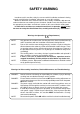
SAFETY WARNING In order to use this machine safely, be sure to read this Installation and commissioning manual carefully before installation, adjustment or use of this machine. Whenever the owner of this machine entrusts disassembly, installation, adjustment or routine maintenance to another person, the owner should ensure that that person read the appropriate precautions and relevant sections of this manual before starting work.
Contents Operators Manual ......................................................................................................................... 1 SAFETY WARNING ......................................................................................................................3 1. SPECIFICATIONS ..................................................................................... 5 2. HOW TO PLAY .......................................................................................... 6 3.
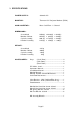
1. SPECIFICATIONS POWER SUPPLY:- 230volts AC MONITOR:- Thomson 52” Projector Monitor (RP52) COIN ACCEPTOR:- Mars CashFlow - 1 Channel DIMENSIONS:Assembled Monitor Cabinet Cycle Assembly Header Assembly 1250(w) 1250(w) 980 (w) 1145(w) x x x x 2430(d) 645(d) 1785(d) 350(d) x x x x 2320(h) 1940(h) 1380(h) 380(h) WEIGHT:Assembled Monitor Cabinet Cycle Assembly Header Assembly ACCESSORIES:- Keys: 411kg 200kg 193kg 18kg (Cash Door) .......................................... 2 (Coin Door) ........
2. HOW TO PLAY This is a new flight game in which the player gains points by riding a humanpowered propcycle and flying freely in the sky. The player flies the propcycle and gains points by hitting and popping floating red balloons. (1) Operation The game is operated by using the handlebars and pedals. Handle: - Handle - Handle - Handle - Handle Backward Forward Left Right = = = = Climb : The cycle gains altitude but loses speed. Drop : The cycle loses altitude but gains speed. Turn Left. Turn Right.
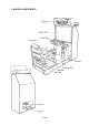
3.
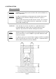
4. INSTALLATION Notes on Installation DANGER NEVER turn the power to the machine ON until installation has been completed. DANGER In order to avoid injury or damage to the machine due to misoperation, ensure that the voltage of the mains supply is 230volts AC. Also, in order to prevent possible electric shocks, be sure that the machine is connected to the mains supply with a securely connected earthed plug.
WARNING This machine is designed for indoor use only. The game must not be installed outdoors or under the following conditions:a. In areas directly exposed to sunlight, high humidity, direct water contact, dust, high heat or extreme cold. b. In locations that would present an obstacle in the case of an emergency, i.e. near fire equipment or emergency exits. c. On an unstable or uneven surface, or subject to floor vibration.
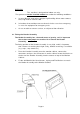
4-2 Connecting the Cycle Assy to the Monitor Cabinet 1, Connect the connectors between the Cycle Assembly And the Monitor Cabinet. 2. Remove 2off Hex Head Set Screws (M8x25), Spring and Flat Washers on each Joint Bracket, turn the Bracket over and refit, finger tight, using the same screws and washers. 3. Push the Cycle Assembly fully up to the Monitor Cabinet, taking care not to trap any wires.
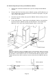
4-3 Removing the Shipping Bracket 1. Remove the two Hex Head Set Screws (M8x16) retaining the shipping bracket to the Cycle Base. 2. Remove the two Hex Head Set Screws (M12x20) retaining the shipping bracket to the Cycle Assembly. 3. Remove the shipping bracket. (Ensure that the bracket and the M8 screws and washers are retained safely for refitting if the machine is moved or transported in the future.) 4. Refit the two Hex Head Screws (M12x20) with washers to the Cycle Assembly and tighten fully.
5. ADJUSTMENTS 5-1 Turning on the Power After the machine has been installed, turn ON the power. The Power switch is located on the rear of the Main cabinet. (See section 3 “Major Components” (page 3).) 5-2 Adjustment Switches The adjustment switches are located inside the coin door. 1. Service Switch Press this switch to obtain game credits without incrementing the play meters. 2. Test Switch Slide this switch “ON” to enter test mode. Test mode allows game testing and the changing of game settings.
5-3 Test Mode 1. Open the coin door and slide the test switch “ON”. The “Menu Screen” will be displayed on the monitor. 2. Select the test required by moving the handle bars up or down. The colour of the selected test will change. 3. Enter the selected test by pressing the start button. Select “EXIT” to return to the “Menu Screen” 4. After testing is completed, ensure that the test switch is returned to the “OFF” position to return to game mode.
5-3-1 Coin Options a. Select item (1) “COIN OPTIONS” on the menu screen, to set the game cost and related settings. b. Move the handle bars up or down to select the required item then press the start button. c. Move the handle bars left or right to change the settings then press the start button to store the new values. d. Select “EXIT” and press the start button to return to the menu screen. Note:- The price of play on this machine is set within the Cashflow Coin Mech.
5-3-2 Game Options a. Select item (2) “GAME OPTIONS” on the menu screen to set the game options. b. Move the handle bars up or down to select the required item then press the start button. c. Move the handle bars left or right to change the settings then press the start button to store the new values. d. Select “EXIT” and press the start button to return to the menu screen. GAME OPTIONS [DEFAULT IN GREEN] DIFFICULTY B ............................. (a) CONTINUE TIME B .........................
5-3-3 I/O Test a. Select item (3) “I/O TEST” on the menu screen. b. Move the handle bars up or down to select the required item then press the start button. c. Move the handle bars left or right to change the settings then press the start button to store the new values. d. Select “EXIT” and press the start button to return to the menu screen I/O TEST DIP SWITCH PEDAL MOTOR LAMP 12345678 .................................... .................................... ....................................
5-3-3-1 a. Switch Test Select “SWITCH” on the menu screen and press the start button. The following screen is displayed. I/O TEST DIP SWITCH 12345678 UP / DOWN : RIGHT / LEFT : START : COIN : SERVICE : 0000 0000 OFF OFF OFF ................................... ................................... ................................... ................................... ...................................
5-3-3-2 a. Pedal Test Select “PEDAL” on the menu screen and press the start button. The following screen is displayed. I/O TEST DIP 12345678 SWITCH PEDAL PEDAL 7FBF READY PRESS START .................... (a) } .................... (b) TO EXIT : PUSH START AND HANDLEBARS UP (a) Pedal rotation When the pedals are rotated in the forward direction the value increases, and when they are rotated in the backward direction the value decreases.
e. When the start button has been pressed, the following screen is displayed. I/O TEST DIP 12345678 SWITCH PEDAL PEDAL C5CF END OK RETRY : PRESS START TO EXIT : PUSH START AND HANDLEBARS UP f. If “OK” is displayed the pedals are correct. If “NG” is displayed there has been a problem in reading the pedal rotation. Press start and repeat steps c) and d) again. If “NG” is still displayed after repeating the test, there is the possibility that the sensor board or sensor sticker is faulty. g.
5-3-3-4 a. Lamp Test Select “LAMP” on the menu screen and press the start button. The following screen is displayed. I/O TEST DIP 12345678 SWITCH PEDAL MOTOR LAMP BUTTON OFF EXIT START : ENTER UP/DOWN : CHOOSE b. When the start button is pressed once, ‘OFF’ changes to ‘ON’ and the start button lamp turns ON. When the start button is pressed again, ‘ON’ changes to ‘OFF’ and the start button lamp turns OFF. c. Select “EXIT” and press the start button to return to the “I/O Test” screen. 5-3-4 a.
5-3-5 a. Sound Test Select “SOUND TEST ” on the menu screen and press the start button. The following screen is displayed. SOUND TEST VOLUME RIGHT SP LEFT SP REQUEST SONG NO. MESSAGE EXIT [0-63] [0-63] 001 START : ENTER / REQUEST / STOP UP /DOWN : CHOOSE LEFT : DECREMENT RIGHT : INCREMENT b. Volume Adjust Move the handle bars up or down to select the item to be changed, and then move the handle bars left or right to change the setting of the selected item. (0 is the quietest / 63 is the loudest.) c.
6. INITIALIZATION Adjustments When Replacing Parts (Initialization) The following adjustments should always be performed after replacing the game PC board, ROM, Steering Assy, Pedal Assy, or Control Pots. The game will not operate correctly if these adjustments are not made. a) Ensure that handle bar assembly is in the neutral position by keeping your hands away from the assembly. b) Slide the test switch “ON” while pressing the service switch. The following screen will be displayed on the monitor.
7. MAINTENANCE Maintenance and repair should only be carried out by competent persons. WARNING • Do not make any alterations to this machine without prior approval. Doing so could cause unforeseeable danger. • Only parts specified by Namco Europe Ltd. should be used when replacing or repairing parts (including screws). • Ensure that power to the machine is turned OFF before commencing any maintenance work (troubleshooting, repairs etc.
7-1 Pedal Pressure Adjustment This game is designed so that the pedal pressure can be adjusted. This will have an effect on the difficulty of the game. At the time of shipment, the pressure is set to a light setting. The mechanism becomes uncovered so take care not to trap hands or fingers in the mechanism 1) Remove the four security screws (M5x12) and remove the upper cover. 2) Remove five security screws (M5x20) and four security screws (M5x12) and remove the right side cover.
7-2 Inspecting or Adjusting the Drive Belt The mechanism becomes uncovered so take care not to trap hands or fingers in the mechanism 1) Remove the three security screws (M5x12) and remove the upper cover. 2) Remove five security screws (M5x20) and four security screws (M5x12) and remove the right side cover. 3) Press the centre of the belt with a push type scale, or pull the centre of the belt with a spring type scale. The drive belt should have 4 to 5mm slack when a force of 500g is applied.
4) To increase the tension, slacken the front nylon nuts (M6) and tighten the rear nylon nuts (M6). To decrease the tension, slacken the rear nuts and tighten the front nuts. Note: To ensure that the flywheel remains parallel within the frame, adjust each nut on both sides by the same amount. 5) After adjustment, turn the pedals three or four times to ensure that the drive belt remains central across all pulleys.
4) Remove the four Pozi head screws (M5x12) and remove the wheel cover. 5) Remove the hexagonal flange nuts (3/8”) on both sides and the four eye bolts which retain the flywheel shaft to the frame assembly. 6) Move the flywheel forward to release the tension on the drive belt, and slip the drive belt off the pedal pulley.
7) Move the flywheel back to disengage it from the cycle frame. Note: When disengaging the flywheel, the link unit will come off the shoulder bolt, so hold it by hand. 8) Lift the flywheel up a little and remove the drive belt from the flywheel pulley. 9) Remove the flywheel together with the entire link unit by withdrawing the assembly from the right hand side. 10) Re-assembly in reverse order.
7-4 Inspecting and Replacing the Pedal Sensor Sticker 1) Remove the top and left side covers (see section 7-2) 2) Remove the two Pozi head screws (M5x10) and remove the sensor PCB. 3) Look through the square cut out and make sure that the sensor sticker is not dirty or damaged. 4) If the sensor sticker is dirty wipe it with a clean soft, dry cloth. If it is damaged it will need to be replaced. 5) Remove the flywheel (see section 7-3). 6) Remove one nylon nut (3/8”) and remove the tension pulley.
7-5 Replacing the Fluorescent Tube DANGER; To prevent electric shock, ensure machine is switched OFF before commencing work. 1) Remove the ten socket button head screws (M5x12), and remove the side vac-forms. (five screws on each vac-form) 2) Remove the two countersunk screws (M5x12) from the bottom of the acrylic. 3) Remove the two socket button head screws (M4x25), and remove the header acrylic retaining bracket. 4) Remove the header acrylic. 5) Replace the fluorescent tube and/or the starter.
7-6 Replacing the Fan Warning: The Front Base Assembly weighs approx. 25kg. It should be handled by at least two people. 1) Remove the four security screws (M5x30). 2) Disconnect and remove the front base assembly. 3) Remove the four security screws (M5x12) and remove the front cover.
4) Remove the three countersunk screws (M5) and remove the fan box front panel. 5) Remove the four M4 Whizz nuts on the rear of the front base wood and remove the fan from the front.
7-7 Replacing the Start Switch 1) Remove the three security screws (M5x12) and lift up the control panel hood. Remove the switch and lamp assembly from the start button and remove the control panel hood. 2) Replace the switch or lamp. Note : When replacing the switch ensure that the wires are replaced to the correct terminals.
7-9 Replacing the Handle Assembly 1) Remove the handle cover. (see section 7-8) 2) Remove the two Pozi head screws (M5x12) with flat and spring washers and remove the control panel base. 3) Dis-connect the handle assembly connector. 4) Remove the four Hex head set screws (M8x16) and remove the handle assembly. 5) Refit in reverse order. Important: After replacing the handle assembly be sure to re-initialize the machine.
7-10 Replacing the Handle Pots. 7-10-1 Replacing the Up/Down Pot 1) Remove the four security screws (M5x12) and remove the front cover 2) Remove the three wires from the pot (note position and colour of wires for re-assembly) 3) Remove the grub screw (M4x8), then slide the pot bracket (A) to the right and pull it forward to remove it. 4) Remove the pot from the bracket and replace with a new one. 5) When replacing the pot, ensure that the grub screw engages on the flat of the pot shaft.
7-10-2 Replacing the Left/Right Pot 1) Remove the handle cover. (see section 7-8) 2) Remove the wires from the pot. (note position and colour of wires for re-assembly) 3) Remove the grub screw (M4x8) 4) Remove the pot from the pot bracket (B) and replace with a new one. 5) When replacing the pot, ensure that the grub screw engages on the flat of the pot shaft.
7-11 Replacing the Pedals 1) Remove the security screw (M5x12) and remove the pedal cover. 2) Loosen the nylon nut (M6) on the crank pin ensuring that no threads are protruding through the nut. (If any thread is protruding , the thread may be damaged in the following step). 3) Turn the pedal so that the nylon nut is at the top. Holding the pedal firmly tap the nut with a hammer to release the crank pin. Once the crank pin has been released the nylon nut can be removed and the crank pin withdrawn.
4) When re-fitting, the crank pin should be inserted from the front (monitor side) when the pedal is directly downward. 5) The crank arm moves 2 ~ 3mm in and out on the shaft when the crank pin is inserted. Move the crank arm to the outside and tighten the nylon nut (M6) NOTE: If the nylon nut (M6) is over tightened damage may occur to the crank arm. Tighten only so that there is no play of the crank arm on the shaft. 6) Refit the pedal cover.
7-12 Replacing the Vibration Proof Rubbers 1) Remove the two security screws (M5x12) and remove the joint cover. 2) Disconnect the connector and remove the three hex head screws (M12x25). 3) Lift the cycle assembly straight up and remove from the base assembly. NOTE: The cycle assembly weighs approx. 45kg. Ensure that at least two people are used to remove the cycle assembly. When replacing the cycle assembly take care not to trap hands or fingers.
6) Remove the eight hex head bolts (M10x25) (with spring and flat washers) and remove the joint base. NOTE: The joint base weighs approx. 20kg so be careful when installing or removing it. 7) Remove the four hex nuts (M12), spring washers (M12) and flat washers (M12) and remove the joint spacer. 8) Remove the four hex head screws (M10x35) (with flat and spring washers) and remove the cross link. NOTE: The narrow pillow-type unit rotates.
9) Remove the two hex head bolts M10x25) (with spring and flat washers) and remove the vibration proof rubber. 10) Replace the vibration proof rubber and re-assemble in reverse order. When installing the cross link, press the bearing against the positioning plate to position it in the forward and backward direction. To position it in the left to right direction, visually place the cross link so that it is nearly in the centre.
7-13 Replacing the Rubber Stoppers 1) Remove the joint base as described in section 7-12. 2) Remove the hex nut and spring washer (M8) and remove the rubber stopper. 3) Replace the rubber stopper and re-assemble in reverse order.
8.
Page 44
ITEM DESCRIPTION PART No 3 Side Cover - LHS 45000977 4 Side Cover - RHS 45000978 5 Crossbar Vac-Form 45000979 6 Handlebar Stem Vac-Form - Front 45000980 7 Handlebar Stem Vac-Form - Rear 45000981 8 Pedal Side Vac-Form - LHS 45000982 9 Pedal Side Vac-Form - RHS 45000983 10 Pedal Cover Vac-Form 45000984 11 Side Indicator Decal 40000347 12 Crossbar Warning Decal 40000348 13 Encoder PCB 14 Pedal - LHS XPC-Pedal-LHS 15 Pedal - RHS XPC-Pedal-RHS 16 Crank Arm - LHS XPC-Cra
Page 46
ITEM DESCRIPTION PART No 1 Steering Shaft 45000954 2 Handlebars 45000955 3 Steering Base 45000957 4 Switch Support Bracket 45000956 5 Handlebar Locating Bracket 45000958 6 Handlebar Bearing Block 45000959 7 Rosta Spring Support Bracket 'A' 45000960 8 Rosta Spring Support Bracket 'B' 45000961 9 Height Pot Locating Bracket 45000962 10 Steering Pot Locating Bracket 45000963 11 Hex Spacer 45000964 12 Steering Bearing Spacer 45000965 13 Bottom Fixing Plate - Steering 4500
ITEM DESCRIPTION ------- Bike Mechanical Assembly - Complete PART No XPC-Bike 1 Flywheel XPC-Flywheel 2 Flywheel Drive Pulley 3 Pulley N168-R03A 4 Drive Wheel XPC-Drivewheel 5 Shim Washer XPC-Shim 6 Drive Belt N168-R06 7 Magnet Holder 22 Pedal Speed Encoder Decal XPC-Flywhldrvpul XPC-Pulley XPC-Drivebelt XPC-Magnetholder Page 48 40000344
ITEM DESCRIPTION PART No 1 Rear Barrier Perspex 39000306 2 Perspex Fixing Bracket 46000009 3 Perspex Fixing Plate 46000010 4 Rear Safety Barrier Clamp 46000014 5 Barrier Pipe Joint 46000012 6 Barrier cushion 46000013 7 Rear Barrier Pipe 46000011 Page 49
Page 50
ITEM DESCRIPTION PART No 1 Main Base Metalwork 45000985 2 Base Step Right 45000986 3 Base Step Left 45000987 4 Coin Tower 45000988 5 Bike Base Surround 45000989 6 Bike Base 45000990 7 Bike Mounting Plate 45000991 8 Bike Rear Base Cover 45000992 9 Bike Rotational Shaft 45000993 10 Bearing Washer 45000994 11 Floor Mat 45000995 12 Floor Mat Closing Bracket 'A' 45000996 13 Floor Mat Closing Bracket 'B' 45000997 14 Instruction Decal Support Bracket 45000998 15 Cabine
ITEM DESCRIPTION PART No 1 Fan Cover Vac-Form 45000934 2 Fan/Speaker Box Wood 37100099 3 Fan Cover 45000935 4 Top Fan Mesh 45000936 5 Bottom Fan Mesh 46000042 6 Speaker Mesh 45000938 7 Speaker Mesh Washer 45000939 8 Fan - Rotary 45000940 9 Fan Warning Decal 40000343 10 Loudspeaker 5½" Full Range - With Shield 62000073 Page 52
ITEM DESCRIPTION PART No 1 Header Wooden Housing 37100097 2 Fluorescent Tube 3ft 98000016 3 Header Acrylic Retaining Bracket - Upper 46000034 4 Header Acrylic 30000230 5 Header Vac-Form with Inset - RHS 45000932 6 Header Vac-Form with Inset - LHS 45000931 7 Header Vac-Form Decal 'NAMCO' 40000266 Page 53
ITEM DESCRIPTION PART No 1 Sub Bass Cabinet 37100100 2 Sub Bass Cabinet Grille 46000035 3 Bass Drive Unit 6½" 62000068 Page 54
Page 55
9.
Page 57
Page 58
Page 59