
Data Sheet
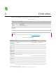

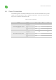
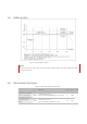
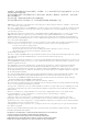
Table Of Contents

4.4
.
Reflow Profile
250
200
100
50
25
0
0
100 250
Figure 4-1. NL04A Reflow Profile
Note:
Solder the module in a single
r
eflow. If the PCBA
r
equi
r
es multiple
r
eflows, place the module on the PCB
during the final
r
eflow.
4.5
.
Electrostatic Discharge
Table 4-4. Electrostatic Discharge Parameters
Peak Temp.
235 ~ 250℃
Pr
eheating
150 ~ 200℃
zone
60 ~ 120s
Reflowzone
>217℃ 60 ~ 90s
Cooling zone
Ramp-up zone
Soldering time
> 30s
Time (sec.)
Name Symb
Temperature: 23 ± 5 ℃
Based on ANSI/ESDA/JEDEC JS - 001 - 2014 2 2000
V
Electrostatic Discharge
(Charged - Device
Model)
217
-1 ~ -5℃/s
1 ~ 3℃/s
50
150
200
Ramp-up zone — Temp.: <150℃ Time: 60 ~ 90s Ramp-up rate: 1 ~ 3℃/s
Preheating zone — Temp.: 150 ~ 200℃ Time: 60 ~ 120s Ramp-up rate: 0.3 ~ 0.8℃/s
Reflow zone — Temp.: >217℃ 7LPH□@60 ~ 90s; Peak Temp.: 235 ~ 250℃ (<245℃ recommended) Time: 30 ~70s
Cooling zone — Peak Temp. ~ 180℃ Ramp-down rate: -1 ~ -5℃/s
Solder — Sn&Ag&Cu Lead-free solder (SAC305)
ol
Reference Level Max Unit
Elect
r
ostatic
Discharge
(Human - Body Model)
VESD
(HBM)
T
emperatu
r
e: 23 ± 5 ℃
Based on JEDEC EIA/JESD22 - C101F
C2 500
VESD
(CDM)
Temperature (℃)