
User's Manual


6
2B. Remove power from the control panel, disconnect the battery wires and replace
the EPROM with the new version.
2C. Power up the control panel and reconnect the battery wires. Enter Direct Address
Program Mode and Cold Start the control panel (refer to the enclosed
programming instructions WI2052 for the procedure).
2D. Download the saved control panel program configuration back into the control
panel or create and download new control panel programming.
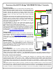
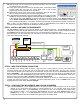
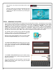
2E. In PCD-Windows Quickloader, select the keypad address to be used for the IBR-
ZREMOTE; change the keypad Type for that keypad address to "RCM" (as shown
in the image at right), select EZ Arm (6 columns to the right on the same screen). In the Keypad Features tab,
check "Disable Code-Required-for-FM-Level 1". Download to the control panel (all IBR-ZREMOTE modules are
factory defaulted as keypad #1). Change the conventional wired burglary keypad that was keypad #1 to keypad #2.
Note: If this is your first installation, we suggest you leave the IBR-ZREMOTE at KP ADDR #1 and change the
conventional wired keypad to ADDR #2 as described in these instructions.
STEP 3: INSTALL AND WIRE THE IBR-ZREMOTE
The IBR-ZREMOTE requires a unique keypad address on the NAPCO keypad bus. The IBR-ZREMOTE is factory
configured as control panel keypad address #1 and as a Napco "Classic" keypad. Place the panel configuration jumper
into CONFIG mode and leave this jumper there for now. The keypads will be configured in step 5.
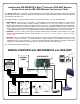
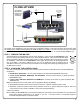
Disconnect power from the control panel (AC and battery) and connect the keypad bus wires as shown below to the
+12V, GND, GRN and YEL terminals.
STEP 4: WIRE THE NETWORK CONNECTION
Use standard CAT5 network cables as follows: Plug one end of a CAT5 cable into an open LAN socket on the
customer's existing router and the other end into an open LAN socket of the ISEE-WAP. Plug one end of a second
CAT5 cable into another open LAN socket on the ISEE-WAP, and the other end into the IBR-ZREMOTE receptacle
labeled "ETHERNET". Then plug one end of a third CAT5 cable into another open LAN socket on the ISEE-WAP, and
the other end into the other IBR-ZREMOTE receptacle located on the right side of the IBR-ZREMOTE. Refer to the
diagram on page 4 if needed. Note: Customer's router must support DHCP.
Reconnect the battery connection and power the control panel. Wait two (2) minutes for all devices to fully power and
complete their network connections. Remember, the panel configuration jumper is set to CONFIG mode, so the
keypads will power up and display "OUT OF SYSTEM".
STEP 5: CONFIGURE THE IBR-ZREMOTE AND KEYPAD ADDRESSES
5A. If the IBR-ZREMOTE is to be keypad address #1 and set as a Napco "Classic" keypad, then set the keypad
address in the conventional wired keypad to keypad address #2 as you normally would using Keypad
Configuration Mode (press 11123 FUNCTION). If you have more than one conventional wired keypad, verify
each address is unique. If not changing the IBR-ZREMOTE, then move the panel CONFIG jumper back to
NORM and go to step 7. If the IBR-ZREMOTE is changing, then the basic procedure is to enter Keypad
Configuration Mode and set the KP ADDR and Keypad Type to the desired values.
Change keypad Type to "RCM"
RJ45
CABLE
MAC Address
(Example:
00-20-4A-80-
81-8B)
1
2 3 4 5 6 7 8 9 10
1
2
GRN
YEL
HEADER
SOCKET
J3
TO PANEL SERIAL PORT (only needed
for NL-MOD CS communication)
RED
BLK
RJ45
CABLE
GND
DATA
BELL
IN0
IN1
IN2
IN3
SUPV.
R.B.
+12V
LOCAL
DNLD
RJ12
CABLE
ETHERNET
ETHERNET
3 WIRE
4 WIRE
CONTROL
PANEL