
Technical Manual


Napco iSecure Security System All technical manuals are available in PDF format at tech.napcosecurity.com 11
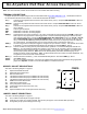
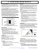
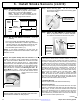
Go-Anywhere Hub Rear Access Descriptions
Note: The rear terminals, headers and sockets are not accessible after wall mounting.
TERMINAL DESCRIPTIONS
Configure all inputs and outputs using the iSecure Cloud Web Portal at www.iSecureByNapco.com. Located at the bottom of
the Go-Anywhere Smart Hub PC board, the 11 terminals are described as follows:
Z7 (‒): Connects to the negative terminal of the two-wire smoke sensor (zone 7). Requires ISEC-2WF-MOD 2-Wire Fire
Sensor Module.
FIRE PR+: Connects to the positive terminal of the two-wire smoke sensor. Requires ISEC-2WF-MOD 2-Wire Fire Sensor
Module.
Z8 (‒): Connects to the negative terminal of the two-wire smoke sensor (zone 8). Requires ISEC-2WF-MOD 2-Wire Fire
Sensor Module.
GND: Common ground terminal.
GRN: Remote Bus connection, see wiring diagram.
YEL: Remote Bus connection, see wiring diagram.
PGM (+): This terminal is a low current continuous +12V output. Wired with the active trigger terminal PGM (‒) below, this
PGM output can be programmed to either toggle on/off or remain momentarily energized (for about 5 seconds)
upon a keyfob button press. Program in KEYFOB SETTINGS, KEY FUNCTIONS column (for Key #3 or Key #4,
select AuxOutput/PGM Toggle or AuxOutput/PGM Momentary). This terminal can be wired to an LED or to the
red (+) of the model RB1000 Relay Board (the RB1000 is a low-current Form-C relay that provides an additional
dry contact output). This RB1000 relay may be used to activate access control devices, locks, etc.
PGM (‒): The active trigger for the PGM (when triggered, changes from open collector to active). This terminal can be wired
to the black (‒) of the model RB1000 Relay Board (see description of terminal PGM (+), above).
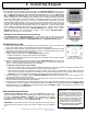
BELL (+): Connect the alarm sounding devices (self-contained sirens, speakers or a mechanical bells) this terminal and
BELL (‒). Any self-contained external siren requiring a 12V supply can be connected. When connecting a me-
chanical bell, it must be supervised using a 2.2k Ohm resistor. To connect 8 Ohm speakers, use a Siren Driver
with the proper polarity observed. Note: Refer to the Standby-Battery Calculation Worksheet (page 72) for
standby and alarm current specifications. Note: In NFPA Household Fire and carbon monoxide installations, only
a single siren or bell can be used on this bell circuit.
BELL (‒): Wire this terminal to the black (‒) of the model RB1000 Relay Board. See terminal BELL (+), above..
16VAC: (see 16VAC, below)
16VAC: AC In (2 non-polarized terminals). Connect to the supplied 20VA TRF12 Class 2 transformer using appropriate
gauge wire. Important: Do NOT connect the wall adapter to a switched AC outlet.
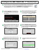
HEADER / SOCKET DESCRIPTIONS
Also refer to the Wiring Diagram on page 79.
J1 Optional Z-WAVE Board insert
J2 Optional Wi-Fi PC Board insert
J3 Wi-Fi PC Board Insert
J4 LTE Radio PC Board insert (for pre-installed LTE radio module)
J5 LTE Radio PC Board insert (for pre-installed LTE radio module)
J7 LTE Radio PC Board insert (for pre-installed LTE radio module)
J9 900MHz Transceiver Board insert
J11 2-Wire Fire PC Board insert
J15 Voice prompt mini-sounder socket
J14 Local keypad socket (reserved for future use)
J16 Siren socket
J19 Optional 345MHz receiver socket (reserved for future use)
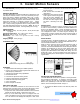
JUMPER / SHUNT DESCRIPTIONS
Also refer to the Wiring Diagram on page 79.
J8 Cut to enable Control tamper as keypad 1 tamper
JP2 Insert shunt on power up to create Cold Start, then remove (see page 61 for the full Cold Start procedure)
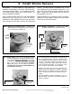
JP4 Configuration jumper (Technical Support use only)
JP4
TIVA
1 2
3 4
5
6
900
CONFIG
spare
Go-Anywhere Hub
"JP4"