
Technical Manual


Napco iSecure Security System All technical manuals are available in PDF format at tech.napcosecurity.com 15
LED jewel pops out, reinsert it with the small index key posi-
tioned at the top.
3. Slide out the lens and install the
replacement.
4. Replace the Lens Support: Slip the
Lens Support under the top guides
with its two tabs straddling the
LED jewel, then push in at the bot-
tom until the Lens Support snaps
into place. Removing Lens Sup-
port.
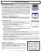
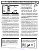
INSTALLATION
An assortment of ''push-thru'' holes is provided in the rear case
for wall or corner mounting. Install the two lithium batteries as
shown in the illustration below. Loosen the Height Lock Screw
and set the board's height scale to the mounted height of the
unit. Retighten the screw. To reduce range if necessary, set
height scale at a higher number than actual mounting height of
unit. Do not point the unit at sources of heat, such as radiators,
space heaters, etc.
WALK TESTING
The LED will light in the Walk-Test Mode only. Allow at least 3
minutes for the unit to settle. Press the Walk-Test Button to ac-
cess the Walk-Test Mode for 5 minutes.
Walk out to the maximum range and walk across the field of
coverage. The LED will light whenever motion is detected.
Check for environmental disturbances with all disruptive devices
(heaters, air conditioners) on and no human activity within the
coverage area. Adjust beams laterally by removing the Lens
Support (see REPLACING THE LENS) and sliding the lens
slightly left or right. To block a problem zone, apply a piece of
lens foil (supplied) to the inside segment of the lens represent-
ing that zone.
SETTING THE OPERATING MODE
The ISEC-MOTION comes set for operation in the Signal Selec-
tive Processing (SSP) Mode. To change to the fixed 2-pulse
bipolar mode for use with the Long-Range Lens (LENS840),
Barrier Lens (LENS818) or other lens with a limited number of
beams, remove the Response-Mode Jumper, J1.
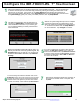
To program the Motion sensor in the iSecure portal, see
page 45.
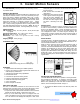
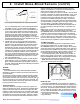
The ISEC-MOTION provides protection by detecting motion
in protected areas.
GENERAL DESCRIPTION
The ISEC-MOTION is an advanced PIR sensor designed for use
with Napco's wireless receivers. The unit is powered by two sup-
plied 3-volt lithium batteries (estimated battery life 3 years).
When battery voltage drops below normal, a low-battery report
will be sent to the receiver (replace with Duracell DL123A, Varta/
Power-One CR123A or Panasonic CR123A only). Coding
switches are not used in the ISEC-MOTION. Each transmitter
has a unique factory-programmed RF ID code (printed on the
unit) that distinguishes itself to the receiver. (Note: Be sure to
enter all numbers and/or letters, including leading zeros, if any).
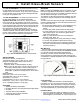
SPECIFICATIONS
PIR Coverage (l x w): 50' x 50' (15.2m x 15.2m) at 20°C (68°
F), typical.
Operating Temperature: 0° to +50°C (32° to 122°F)
Mounting: Wall or corner, 10' (3m) max.
Dimensions: 4.5'' x 2.5'' x 1.7'' (11.4cm x 6.4cm x 4.3cm)
(HxWxD)
Shipping Weight: 6.4oz (181gm)
STANDARD LENS
FEATURES
Signal Selective Processing for reliable operation
Unique circuit design protects against false alarms due to
radio-frequency interference
Vertical and horizontal aiming capabilities
Dual-element sensor
Lens Bank of optional accessory lenses
Large lens area assures high sensitivity
Small size with ample wiring space
Corner mountable
Built-in Tamper microswitch
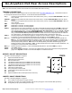
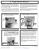
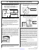
REPLACING THE LENS
The lens is ''sandwiched'' between the front case and a Lens
Support insert, which also serves to hold the LED jewel in place.
To install one of the accessory lenses, proceed as follows.
1. To open the case, insert a small screwdriver in the slot at the
bottom and push up slightly. Remove the front cover.
2. Push up on the lower edge of the Lens Support until it is
clear of its retainers, then pull out the support from the bot-
tom. Be careful not to dislodge the LED jewel. Note: If the
3. Install Motion Sensors
Standard Lens coverage pattern for 6' mounting height.
PUSH
UP
LENS
SUPPORT
LED
JEWEL