
Technical Manual


18 All technical manuals are available in PDF format at tech.napcosecurity.com Napco iSecure Security System
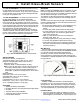
5. Install Window / Door Transmitters
3. Select transmitter location. Avoid
mounting the transmitter near the
floor. Low level mounting can
reduce transmission range and may
subject the transmitter to damage.
4. Install transmitter Mounting Plate
and Magnet. Use #6 flat-head
screws or double-sided tape
(supplied) to secure. Do not over-
tighten the screws securing the
Magnet Housing. Observe internal
magnetic reed switch alignment
marks on both the transmitter Front Cover and Magnet
Housing. Mount Magnet up to 5/8" of the transmitter
Front Cover. If mounting the Magnet with double-
sided tape, the Magnet Housing tabs may optionally
be removed--use a utility knife only--do not bend or
break off tabs (see Fig. 2).
5. Make note of the 6-digit ID code with checksum
digit printed on the inside sticker. Be sure to make
note of ALL numbers and/or letters, including leading
zeros, if any. This data will be used when program-
ming the Go-Anywhere Smart Hub in step 7.
6. Close the transmitter case. Close by engaging the
retaining tabs near the reed switch, then snapping the
Front Cover to the Mounting Plate.
7. Program the Go-Anywhere Smart Hub. Each
transmitter has a unique factory-programmed ID code
that distinguishes itself to the receiver. The ID code is
located on the rear of the Mounting Plate. Note: The
ISEC-DW-XMITTERs included with the ISEC-KITs are
pre-programmed; only new transmitters require the
following programming steps: Enter (a) the zone
number to which the transmitter will be mapped; (b)
the 6-digit ID code with checksum digit; and (c) the
wireless point number. See the Go-Anywhere Smart
Hub installation instructions for how to enter the ID
code and checksum digit; be sure to enter all numbers
and/or letters, including leading zeros, if any.
Caution: Changes or Modifications not approved by
NAPCO may void the user's authority to operate the
equipment. This device may not cause interference.
This device must accept any interference, including inter-
ference that may cause undesired operation of the de-
vice.
*Note: Plastic housing and PCB design may vary from images in this document.
GENERAL DESCRIPTION
The ISEC-DW-XMITTER is a low profile window/door
transmitter designed for use in Napco iSecure wireless
systems. Used with the supplied magnet, the transmitter
functions as a window/door sensor. The ISEC-DW-
XMITTER is powered by a 3-volt lithium battery
(Energizer CR2032 or Duracell DL2032), that powers the
transmitter for up to 5 years. When the battery cell
voltage drops below normal, a low-battery report is sent
to the Go-Anywhere Smart Hub and " E05" (followed
by the zone number) will appear on the keypad display.
INSTALLATION
The PC board is factory installed in the transmitter front
cover and must not be removed. The magnet and trans-
mitter can be mounted in any orientation as long as the
alignment marks are placed side-by-side and the magnet
is placed up to 5/8" of the transmitter, depending on
mounting surface (for reference purposes in this text, the
transmitter will be considered oriented with the reed
switch at the top, as shown in Fig. 1).
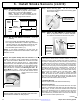
1. Open the case. Remove the ISEC-DW-XMITTER
transmitter cover from its Mounting Plate by pressing
the tab and lifting the Mounting Plate from the cover.
2. Remove silk strip to activate battery cell. Battery is
preinstalled. Ensure cell remains inserted in its holder
after removing silk strip. Note: When replacing a
weak battery, always remove the old battery from the
edge of the battery holder without touching its metal
terminals. Always observe polarity; with the positive
(+) terminal facing up, press the cell into the holder
(see Fig. 1). Do not insert upside down.
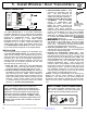
Fig. 2. Remove Mag-
net Housing tabs with
utility knife only.
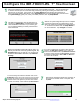
APPLY LABEL OVER SCREW HEAD
Place small individually supplied label (.375"
dia., part # LA2867LF) over screw head (see
arrow) to prevent shorting battery terminals.
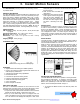
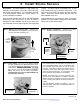
Fig. 1. ISEC-DW-XMITTER Component Parts*
TRANSMITTER MAGNET
Alignment
Mark
DL 203 2 o r
CR 203 2
Reed Switch
Alignment
Mark
Battery
Holder
ID Code
MOUNTING PLATE PC BOARD INSIDE THE FRONT COVER MAGNET HOUSING
This device complies with Part 15 of the FCC
Rules. Operation is subject to the following two
conditions: (1) this device may not cause harmful
interference, and (2) this device must accept any
interference received, including interference that
may cause undesired operation. Caution: Chang-
es or modifications not expressly approved by man-
ufacturer could void the user's authority to operate
the equipment.