
Technical Manual


24 All technical manuals are available in PDF format at tech.napcosecurity.com Napco iSecure Security System
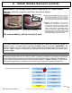
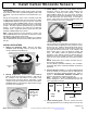
7. Install Heat Sensors (cont'd)
Step 5. Reinstall the ISEC-HEAT into the mounting base.
Insert the ISEC-HEAT into the base and turn the top clockwise
while holding the base stationary until the ISEC-HEAT gently
snaps into place.
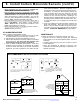
Step 6. Map the ISEC-HEAT Transmitter
Referring to the installation instructions for the Hub and
keypad in use, enter the following:
The zone to which the transmitter will be mapped.
Note: This zone must be programmed as a Fire Zone.
The 6-digit RF identification number / 1 digit checksum
number printed on the transmitter (include all numbers
and/or letters and leading zeros, if any);
The transmitter point number ("1").
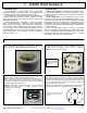
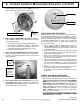
Step 7. Testing the system
Test system with unit mounted. If the system is monitored,
notify the central station of the impending test.
The rate-of-rise feature may be tested by a quick application of
heat from any convenient source. A portable hair dryer is
recommended. However, do not apply heat that exceeds the
fixed temperature rating of the detector. If the fixed
temperature is exceeded, the center disk of the detector will
drop and the detector MUST be replaced.
Apply the heat until the local alarm sounds. Verify that the
ISEC-HEAT has triggered the correct zone and that the correct
report has been transmitted to central station. Wait a few
minutes and reset the fire circuit. Ensure that the system
returns to a normal status.
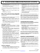
WARNINGS
HEAT DETECTORS ARE NOT LIFE SAFETY DEVICES:
USE FOR PROPERTY PROTECTION ONLY.
WHERE LIFE SAFETY IS REQUIRED, SMOKE
DETECTORS MUST ALSO BE USED.
BATTERY BACK-UP: HEAT DETECTORS SHOULD BE
ELECTRONICALLY SUPERVISED WITH BATTERY
BACKUP AT THE HUB.
THE RATE-OF-RISE MECHANISM MAY BE SUBJECT
TO REDUCED SENSITIVITY OVER TIME. ANNUAL
TESTING OF THE RATE-OF-RISE OPERATION IS
RECOMMENDED.
REFER TO NFPA STANDARD 72 FOR APPLICATION
REQUIREMENTS, TESTING AND MAINTENANCE.
DO NOT PAINT THE ISEC-HEAT.
A TAMPER ZONE TROUBLE WILL RESULT WHEN THE
BATTERIES ARE REPLACED.
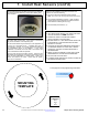
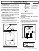
ENSURE THIS
BOX IS
1 INCH
X
1 INCH
MOUNTING
TEMPLATE
See page 49 for full programming information