
Technical Manual
Napco iSecure Security System All technical manuals are available in PDF format at tech.napcosecurity.com 31
10. Install Keyfobs
The ISEC-KEYFOB is a multifunction pendant/keychain
transmitter compatible with Napco iSecure-Series wireless sys-
tems. It serves as an area arm/disarm device with two auxiliary
functions, and may be used as a police panic and/or auxiliary
emergency transmitter. A 3V Lithium coin cell battery powers
the ISEC-KEYFOB transmitter (use type CR2032 or Duracell
DL2032 only; use of another battery may present a risk of fire or
explosion). A flashing LED indication signals a low-battery
warning to replace the unit.
The ISEC-KEYFOB leaves the factory as a remote area arm/
disarm transmitter with two Auxiliary buttons, A1 and A2. Auxil-
iary functions are selected by programming keyfob Aux 1 and
Aux 2 options: None, Panic, Instant , Aux Output Toggle, Aux
Output Momentary, Arm Stay or Bypass Interior.
Note: The Aux 1 Button and Aux 2 Button must each be held
down for approximately 2 seconds before the respective signal
will be sent. The LED will light while the unit is transmitting.
LOW-BATTERY CHECK. THE BATTERIES ARE CHECKED
AUTOMATICALLY DURING ANY TRANSMISSION. A LOW-
BATTERY CONDITION WILL CAUSE THE LED TO COME ON
AND START PULSING FOR APPROXIMATELY 30 SECONDS;
A LOW-BATTERY REPORT WILL BE SENT TO THE RECEIV-
ER.
SPECIFICATIONS
Electrical Ratings
Input Power: Powered by a 3-volt lithium battery.
Operating Frequency: 319.5Mhz
REQUIRED PROGRAMMING
The following information is required for each unit. See page
52 for full programming information.
An assigned keyfob trans-
mitter number
Area number(s) to which
transmitter is applicable
The 6-digit RF ID code with
checksum digit printed on the transmitter (enter all numbers
and/or letters, including leading zeros, if any)
Aux-1 option and Aux-2 option
BATTERY REPLACEMENT
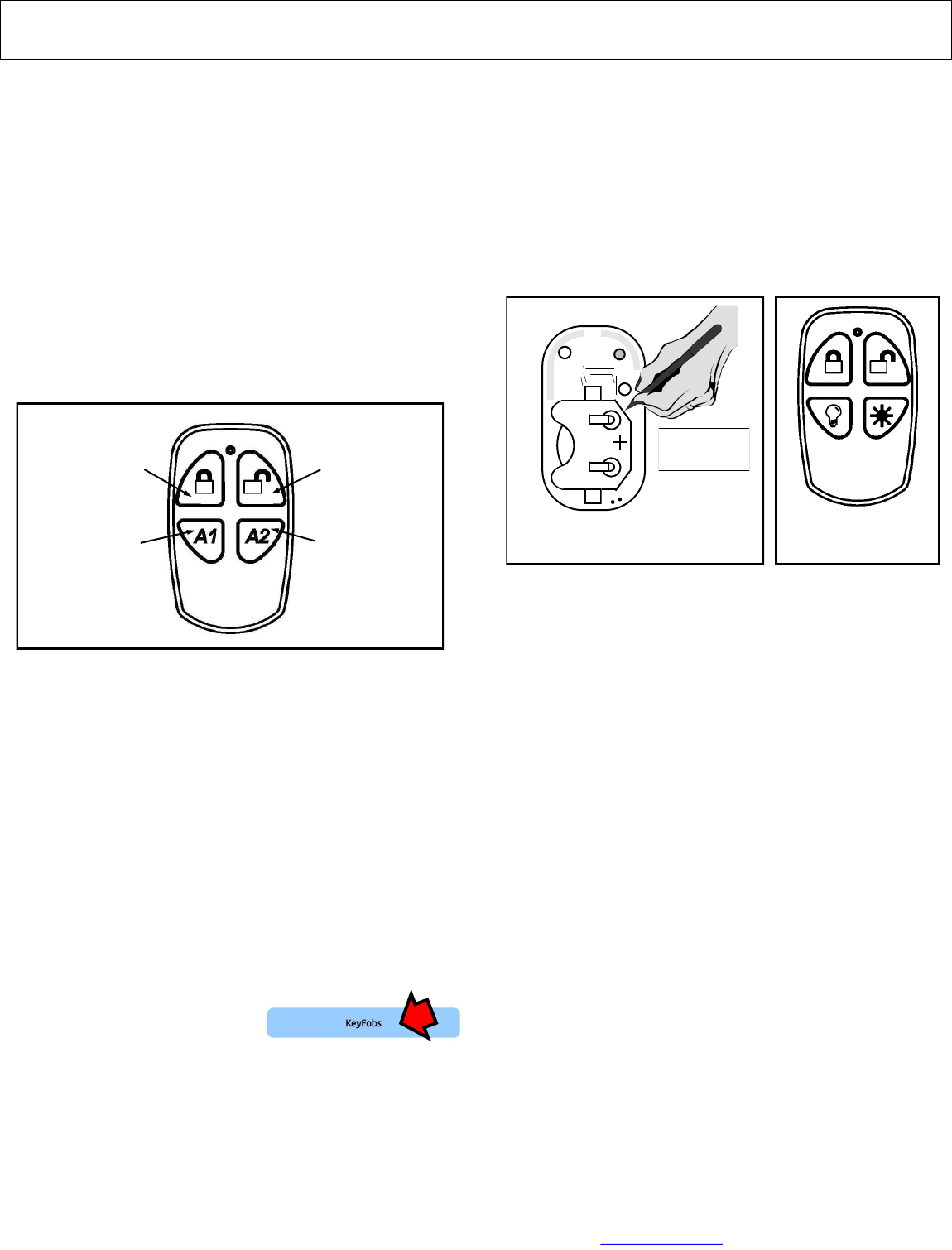
1. Remove the keyring from the keyfob case.
2. Carefully insert the edge of a small coin in the notch locat-
ed in the bottom right corner of the keyfob (near the key
ring loop). Open the case by gently twisting the coin. Lift
off the top cover.
3. With the bottom half of the keyfob facing upwards, carefully
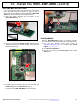
remove the circuit board.
4. On the bottom side of the circuit board, push the battery
out of its metal holder with a sharp pencil. The battery will
slide out of its holder as shown in the image below. Note
the orientation of the battery polarity, with its positive side
up, before fully removing the battery.
5. Replace with a new battery, positive (+) side up, by slid-
ing the battery into its metal bracket. Be certain of battery
polarity before installation.
6. Reassemble the case by first placing the circuit board,
battery side down, into the keyfob base. Place the top of
the keyfob (with its rubber button/gasket in place) on the
keyfob base and press to snap the two keyfob pieces to-
gether.
7. Test the keyfob operation.
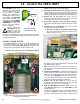
BUTTON REPLACEMENT
Factory supplied auxiliary buttons can be installed to operate
other items, such as outdoor lights. Install as follows:
1. Open the keyfob as per the Battery Replacement instruc-
tions (above) step 1.
2. With the top cover off, lift and remove the rubber buttons
from the inside of the top cover.
3. Replace the rubber buttons with the auxiliary buttons,
(shown above) reassembling the keyfob in the reverse
order of disassembly.
4. Test the keyfob operation.
Battery Replacement: Top View
of Bottom Circuit Board
© NAPCO
06022
2032
Insert pencil and
push battery out of
holder as shown
Button Replacement:
Auxiliary buttons
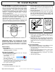
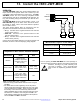
Factory-Supplied Functions: Arm, Disarm, Aux. 1 and Aux. 2
ARM
AUX. 1
DISARM
AUX. 2