R Publicly traded on NASDAQ INSTALLATION INSTRUCTIONS Symbol: NSSC FREEDOM F-64 CONTROL PANEL/COMMUNICATOR For use with the Freedom F-64TP Wireless Touchpad, F-64TPG Garage Door Touchpad, the F-64TPBR Bedroom Touchpad, F-64TP-H Hardwire Touchpad and the F-64PROG Stay/Away Programmer SYSTEM READY 10/03/06 Freedom F-64TP Touchpad © NAPCO 2006 12:03 AM F-64PROG Programmer WI1501A 9/06
THIS MANUAL INCLUDES FEATURES WHICH ARE ONLY AVAILABLE IN THE FREEDOM F-64 CONTROL PANEL FIRMWARE VERSION 30 OR LATER.
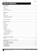
WI1501A 9/06 Page 3 TABLE OF CONTENTS INTRODUCTION ....................................................................................................................................................................... 4 General Description ................................................................................................................................................................... 4 Features ...........................................................................................
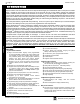
Page 4 WI1501A 9/06 INTRODUCTION GENERAL DESCRIPTION Napco's Freedom F-64 is a state-of-the-art microcomputer-based burglary and residential fire alarm control panel of modular design. Integrally an 8-zone panel, it will support up to 64 zones with the use of zone doubling, optional zone expansion modules, wireless receiver modules and/or Freedom 64 Touchpads. Each panel includes an integral digital communicator.
WI1501A 9/06 Page 5 SPECIFICATIONS Freedom F-64 Control Panel Operating Temperature: 0-49°C (32-120°F) Input Power: 16.5-18.0 VAC via CLASS 2 Plug-In 20VA, 40VA or 50VA Transformer Loop Voltage: 10-13Vdc Loop Current: 3mA without Zone Doubling, 2.4mA with Zone Doubling using a 2.2K Ohm end-of-line resistor (Model EOL2.2K); 5mA for 2-wire smoke-detector zones; 1.4 mA using a 3.9K Ohm resistor (Model EOL3.
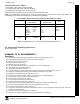
Page 6 ORDERING INFORMATION System Components F-64: Residential UL-Listed Burg and Fire Control Panel F-64PROG: 32-Character LCD Burg & Fire Programmer F-64TP: Wireless Touchpad F-64TPG Garage Door Touchpad* F-64TPBR Bedroom Touchpad F-64TP-H Hardwired Touchpad* Ordering Information Optional Accessories and Peripherals GEM-EZM8: 8 Zone Expansion Zone Module GEM-EZM4/8: 4-16 Zone Expansion Zone Module* GEM-RECV8: Wireless Receiver, 8 Zones GEM-RECV16: Wireless Receiver, 32 Zones GEM-RECV96: Wireless Rece
WI1501A 9/06 Page 7 Smoke Detectors, 4-Wire: 1. ESL 445AT, 445C, 445CT, 445CR, 445CRT 2. Hochiki America SLG-12 with YBC-RL4-RA Base 3. System Sensor 2312/24T; 1412; 1412TH; 2412TH Subtract total smoke-detector alarm current from available standby current. Note: Any normally-open devices that do not require power from the control panel, such as pull stations and thermostats may be used if acceptable to the Authority having Jurisdiction.
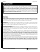
Page 8 WI1501A 9/06 INSTALLATION CAUTION: This equipment generates and uses radio-frequency energy. If not installed using conventional installation practices for RF devices, it may cause interference to radio and television reception. It has been tested and found to comply with the limits for a Class A computing device pursuant to Subpart B of Part 15 of FCC Rules, which are designed to provide reasonable protection against such interference.
WI1501A 9/06 Page 9 Wiring Wire Touchpad(s), zones, expansion zone modules and output devices as shown on the Wiring Diagram. Note that the Wiring Diagram contains important information not available elsewhere in this manual. CAUTION: Do not run telephone wiring near speaker wires; do not run keypad / Touchpad wiring with loop wiring.
Page 10 WI1501A 9/06 TESTING THE SYSTEM After installation is completed, test the system as follows. 1. Call the central station to inform them of the test. 2. Initiate an alarm, preferably on a zone that activates a steady siren, and verify proper signalling. 3. Call the central station to confirm their receipt of a good transmission. Note: Be sure to test all enabled Touchpad panics. Signal Strength Testing/Wireless Systems To test the operation of wireless transmitters, proceed as follows.
WI1501A 9/06 Page 11 WIRING CONNECTIONS BATTERY 7 TRANSFORMER (The following applies to installations in the United States of America): Connect a 16.5 VAC Transformer to Terminals 1 and 2, using a wire of #18 AWG. or larger at a distance of 15 ft. or less from the control panel. NOTE: Do not connect to a switched outlet. SIREN/BELL POWER Connect the alarm sounding devices (self-contained sirens, speakers or a mechanical bell) to Terminals 3 and 4.
Page 12 WI1501A 9/06 REMOTE BUS NOTE: Refer to the EZM Installation Instructions for specific wiring information. REMOTE BUS ADDITIONAL EZMs 1. 2. 3. 4. 5. 6. 7. AVAILABLE DEVICES AVAILABLE DEVICES KEYPADS: GEM-RP2AS & GEM-RP1CAe2 1.
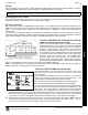
WI1501A 9/06 Page 13 BASIC ZONE CONFIGURATION EZ ZONE DOUBLING TM CONFIGURATION The control panel zone configuration may be expanded from 8 to 16 zones without the use of EZM Modules. To do so simply select “EZ Zone Doubling” in programming (refer to the F-64 Panel Programming Instructions WI1502) and connect zones as shown above. NOTE: If both zones in a zone-pair configuration (ex: zones 1 & 9 in the above diagrams) are to be used, then normally closed devices must be wired to both zones. The 3.
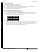
Page 14 WI1501A 9/06 4-WIRE SMOKE DETECTORS Wiring Connections: 4-Wire Smoke Detectors & 2-Wire Smoke Detectors 4-WIRE SMOKE DETECTOR WIRING The F-64 Panel can use conventional 12 VDC 4-wire smoke detectors. To use them, select fire zone programming option and do not select 2-wire smoke detector programming option for the desired fire zone (refer to the F-64 Panel Programming Instructions). Set JP3 to the position as shown, if zones 7 or 8 are to be used.
WI1501A 9/06 Page 15 TELEPHONE LINES RING TIP RING TIP Model 368 Cord RING TIP When communicating to central station and during downloading, the control panel seizes the telephone lines from the house phones, rendering them inoperative during communication. Upon completion of central station communication, the telephone line is restored to the house phones.
Page 16 WI1501A 9/06 KEYPAD / TOUCHPAD MESSAGES The F-64PROG Programmer and Touchpads can display the below messages. Note: See page 6 for a listing of the keypad / Touchpad specific User Guides available. These User Guides contain more details regarding the various messages. SYSTEM READY - All zones operating; system can be armed. 1 through 4 = Area. SYSTEM TROUBLE/E06-NN SERVICE. RF receiver response trouble. NN = receiver number. ARMING YYY/XXX SECONDS - Exit delay in progress.
WI1501A 9/06 Page 17 GLOSSARY The Freedom 64 control panel is capable of utilizing a combined total of 7 keypads and/or Touchpads, with a maximum of 4 Freedom Touchpads assigned to addresses 1-4. The balance can be any of NAPCO's Gemini "K Series" keypads assigned to addresses 5-7. (Note: Any Gemini "K Series" keypads installed in the system would possess limited functionality, and should only be used to view system status).
Page 18 WI1501A 9/06 OUTPUT WIRING REMARKS Alarm Output (Burg.) 3(+) & 4(–) Single Bell Output; program Alarm Output for Burg. See System Options in the Programming Instructions WI1502. Pulse Alarm Output (Pulsed) PGM1 Output 3(+) & 4(–) Single Bell Output; program Pulsed Output for Fire. See System Options in the Programming Instructions WI1502. 5(+) & 7(-) PGM2 Output 5(+) & 8(-) Programmable Output. See System Options in the Programming Instructions WI1502. Programmable Output.
WI1501A 9/06 Page 19 Arm if not closed at end of window. When the start time is reached, the display will notify the occupants that an Auto-Arm will be initiated in the notification period length of time. After that period has expired, a 15 minute period will count down to Auto-Arm with the sounder pulsing. Auto-Arming may be canceled by arming and then disarming the panel. An Auto-Arm will be reported as User 33.
Page 20 WI1501A 9/06 lay or the "Pre-Alarm Warning", then no report will be sent and no messages will be displayed at the keypad/Touchpad. If the area is disarmed during the Abort-Delay, then an "Alarm Canceled' will be displayed at the keypad/Touchpad and no report will be sent. If the area is disarmed during or within the Cancel Window Duration, then an "Attempting to Cancel" will be followed by an "Alarm Canceled" for a successful cancellation.
WI1501A 9/06 Page 21 Default Code of "456789". Press RESET to exit the EZ Program Mode. Access the address location "Cold Start" (see the Programming Instructions WI1502), then press the U button. Data Format Ask the central station which of these formats to use: Two-Digit or 4/2 Format - Some central-station receivers require that a four-digit Account Code followed by a two-digit Alarm Code be sent in each report.
Page 22 WI1501A 9/06 Day Zone (Open; Short); Alarm on Day Zone; Disable Auto-Reset on Day Zone; Reset Day Zone with Arm/Disarm Only; Day Zone Trouble on Open A Day Zone will give an audible and visual indication at the keypad/Touchpad if there is a problem on the loop while disarmed. Openand short-circuit conditions are programmed separately, by zone. This feature may be used to warn of a problem (a break in a window foil, for example) during the day, when the panel is not normally armed.
WI1501A 9/06 Page 23 "ACTIVATE DIALER TEST Y/N" is displayed and then press YES to initiate the transmission of a Test Timer signal. Note: Test Timer reporting codes and Report Test Timer on Telco1 or Telco 3 must be programmed. See glossary entry Test Timer. Direct Address Program Mode See Dealer Program Mode Disable Call Waiting (Touch-tone® Dialing Only) A digital communicator connected to a telephone line with Call Waiting may be disrupted by this feature.
Page 24 WI1501A 9/06 E19 - Lug E19 is the Listen in Lug. It is an input and when it is forced low the panel will silence the keypad/Touchpad sounder and bell outputs so that the Veri-phone can listen to activity at the residence. See Veri-Phone (WI783): Silence All Outputs During Audio Session. Use Napco Part number "WL1" for field wiring. Easy Exit While armed in the Interior Mode, Easy Exit can be initiated by pressing STAY.
WI1501A 9/06 Page 25 Enable Telephone Line Fault Test Enable Line Fault Test will cause the panel to monitor the phone line. A failure will display as "SYSTEM TROUBLE/E-08 SERVICE" for Telco Line Fail. Program this system trouble to activate the Burglary Output. Enable 2-Count Swinger Shutdown See Swinger Shutdown Exit/Entry Delay; Exit/Entry 1; Exit/Entry 2; Entry Relay Delays permit exit and entry through the Entry/Exit Zone(s) after the system is armed without setting off an immediate alarm.
Page 26 WI1501A 9/06 display and pulsing sounder. An open circuit on the Fire Zone will identify a trouble and cause flashing "SYSTEM TROUBLE/E41-00 SERVICE" LCD display and pulsing sounder after a 10-second delay. The sounder may be silenced by pressing RESET. The LED will go off within 30 seconds after reset if the alarm or trouble is cleared. For Smoke-Detector Reset, see Alarm Outputs. Fire or Keypad Fire can be made to trip an alarm or report to Central Station.
WI1501A 9/06 Page 27 Keypad Area Assignments see Touchpad/Keypad Area Assignments Keypad Jumpers see keypad Installation Instructions Keypad / Touchpad Features The following programmed system features will activate only if they have also been enabled at the keypad.
Page 28 WI1501A 9/06 Number of Rings Before Pickup (Answer on Ring) See Callback-Method Download One-Button Arming See Easy Arming Opening Report; Opening Report Only After Alarm Report (Do not program for UL installations). Opening and closing reports are generally used in commercial installations.
WI1501A 9/06 Page 29 a Priority Zone must be corrected before the panel can be armed. Any zone may be selected as a Priority Zone. A zone in trouble that is neither a Priority Zone nor an Auto-Bypass Zone will cause an alarm on arming. Priority Zone with Bypass A Priority Zone that will permit arming if the priority condition is bypassed. If the system is so programmed, the zone will auto-bypass and (optional) the condition will be reported to a central station.
Page 30 WI1501A 9/06 is available, it is included in the Recent Closing transmission. Note: Recent Closing transmissions are not sent for fire alarms. Report Telco 1; Report Telco 3 (Double or Split Reporting) Alarms, alarm restores, troubles and trouble restores may be selected individually for each zone. Violation of a zone selected to report will communicate the code(s) selected for that zone to the central station. Normally, Report Telco 1 is used to report to the central station.
WI1501A 9/06 Page 31 Smoke Detectors; 2-Wire Smoke Detectors; Wireless Smoke Low Battery Resound Connect smoke detectors as shown in the diagrams. The "Fire Power" (Terminal 25) is used to reset the smoke detectors. Two-Wire Smoke Detectors Two-wire smoke detectors may be used only on Zones 7 and 8. Up to 10 compatible 2-wire smoke detectors may be wired to each zone. In Residential applications, program Pulse Alarm Output.
Page 32 WI1501A 9/06 System Troubles (Global and Area); Wireless Low Battery; Wireless Supervisory System troubles may be programmed to report to any telephone number and/or activate any output. Also program Subscriber ID Numbers, Telephone Numbers, and Report Codes for each system trouble. 2-Wire, 4-Wire Smoke Detectors See Smoke Detectors 24-Hour Zone A zone selected for "24-Hour Zone" that provides protection at all times, whether or not the system is armed.
WI1501A 9/06 Page 33 Time Selection The following times are programmable: TIME(1) PGM2 OUTPUT TIMEOUT UNITS MIN. MAX. PROG. TIME UNTIMED(2) PGM2 OUTPUT ACCESS CONTROL TIME SEC. 4 MIN., 15 SEC. (255 SEC.) ALARM OUTPUT MIN. UNTIMED(1)(2) PULSE-BURG OUTPUT MIN. UNTIMED(1)(2) PGM1 OUTPUT MIN. UNTIMED(2) ABORT DELAY SEC. 4 MIN., 15 SEC. (255 SEC.)(3) 63.25 SEC. (255 QTR-SEC.)(3) CHIME TIME SEC. AC-FAIL REPORT DELAY 10 MIN. 42 HR., 30 MIN. (2550 MIN.) EXIT DELAY SEC. 4 MIN., 15 SEC.
Page 34 WI1501A 9/06 If a programmed zone goes into alarm, the Touchpad/keypad sounder will activate and will remain activated until the RESET button is pressed or the system is disarmed. Trouble; Fire Trouble An abnormal zone condition (a break in a normally-closed loop; a short on a normally-open loop; or either on an end-of-line-resistor supervised loop) when disarmed. Trouble on a Burglary Zone is automatically displayed at the Touchpad/keypad unless Disable Zone Fault Scrolling is programmed.
WI1501A 9/06 Page 35 Zone Number on Pulse Alarm See Data Formats: Two-Digit Format Zone Response Time (750mS required for UL installations) Loop response is the amount of time in milliseconds (mS) that a normally-closed circuit must remain open, or a normally-open circuit must remain closed, to trigger an alarm. The slower the loop response, the more immune the system will be to intermittents ("swingers").
Page 36 WI1501A 9/06 STANDBY-BATTERY CALCULATION WORKSHEET Use the procedure given below to determine the required standby battery capacity in Ampere-Hours (AH). Note: It is not totally accurate to merely multiply the combined standby current (in amperes) by the standby time (in hours) to obtain the battery capacity (in ampere-hours), since other factors (control-panel charging capabilities, temperature, battery condition, etc.) affect battery operation.
WI1501A 9/06 Page 37 WIRING LEGEND Should removal of the circuit board be necessary, use this wiring legend to relocate wire leads to their proper terminals. Enter wire identification number or color code in WIRE NUMBER column and enter wire function in DESCRIPTION column (optional). TERMINAL WIRE NO.
Page 38 WI1501A 9/06 CP-01 Quick Reference Chart--SIA False Alarm Reduction Feature Description Programming Address Location CP-01 FEATURES are enabled with one global selection in the panel. Enabled in EZ Programming Exit Delay. Minimum allowed programmable Exit Delay time is 45 seconds. Default is 60 seconds. If an attempt is made to change the Exit Delay time to less than 45 seconds the time will be entered as 60 seconds. The maximum programmable time is 255 seconds.
WI1501A 9/06 Page 39 Duress Code. The panel will not allow duplicate User Codes to be programmed. Every user program code may now be selected as an Ambush Code for Area 1 or Area 2 by entering a _5 in the Area 1 Options or Area 2 Options respectively. Note: Keypad(s) must be enabled for Ambush. Cross Zoning. Required Option for cross zoning with either programmable time period or specified by manufacturer. Default is disabled.
Page 40 WI1501A 9/06 F-64 FACTORY DEFAULT DESCRIPTION Out of Box Panel Operation The following describes the new panel factory defaults: The new SIA CP-01 compliant versions of the F-64 panels have a factory program that allows a locally functioning alarm panel out of the box, programmed with all the non-reporting features required by the SIA CP-01 standard. The new versions of the panels are manufactured with the following factory programmed features: 1. 2. 3. 4. 5. 6. 7. 8. 9. 10. 11. 12. 13. 14. 15.
WI1501A 9/06 1. 2. 3. 4. 5. 6. 7. 8. 9. 10. 11. Page 41 Auto Reset and Swinger Shutdown are removed from burg zones. 1422-bit 6 "Chirp Output on Keyfob Arm/Disarm" is enabled. 1424-bit 0 "Automatic Interior Bypass/Easy Exit" is enabled. 1423-bit 7 "Select Alarm Output for Keyfob Chirp" is enabled. 2053-bit 0 "Exit Time Restart" is enabled. 2053-bit 1 "Sound Alarm on Exit Error" is enabled. 2053-bit 2 "Report Digital Dialer Exit Error/Recent Closing" is enabled.
Page 42 WI1501A 9/06 FCC STATEMENT This equipment generates and uses radio-frequency energy and, if not installed and used properly, that is, in strict accordance with the manufacturer's instructions, may cause interference to radio and television reception.
WI1501A 9/06 Page 43 FREEDOM F-64 WIRING DIAGRAM FREEDOM F-64 Wiring Diagram L NAPCO Security Systems Freedom F-64 Installation Instructions
Page 44 WI1501A 9/06 NAPCO LIMITED WARRANTY NAPCO SECURITY SYSTEMS, INC. (NAPCO) warrants its products to be free from manufacturing defects in materials and workmanship for thirty-six months following the date of manufacture. NAPCO will, within said period, at its option, repair or replace any product failing to operate correctly without charge to the original purchaser or user.