INSTALLER: THESE INSTRUCTIONS MUST BE CONVEYED TO AND REMAIN WITH THE HOMEOWNER. CERTIFIED UNDER CANADIAN AND AMERICAN NATIONAL STANDARDS, CSA 2.33, ANSI Z21.
TABLE of CONTENTS Vermiculite Charcoal Embers Charcoal Lumps PG 2-4 INTRODUCTION Warranty General Instructions General Information Care of Glass & Plated Parts PG 21 22 OPTIONAL FAN INSTALLATION / GD36 THERMOSTATIC SENSOR CONTROL 23 OPERATION / MAINTENANCE 5 - 12 VENTING Venting Lengths Air Terminal Locations Typical Vent Installations Special Vent Installations Operating Instructions Maintenance 13 - 18 INSTALLATION 24 Wall and Ceiling Protection Using Flexible Vent Components Fireplace Vent Co
NAPOLEON gas fireplaces are manufactured under the strict Standard of the world recognized ISO 9001 : 2000 Quality Assurance Certificate. NAPOLEON products are designed with superior components and materials, assembled by trained craftsmen who take great pride in their work. The burner and valve assembly are leak and test-fired at a quality test station.
GENERAL INSTRUCTIONS THIS GAS FIREPLACE SHOULD BE INSTALLED AND SERVICED BY A QUALIFIED INSTALLER to conform with local codes. In absence of local codes, install the BGD42 to the current National Fuel Gas Code, ANSI Z223.1, or the current CAN/CGA B149, Installation Codes.
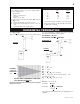
FIGURE 1 VENTING VENTING LENGTHS Use only Wolf Steel or Simpson Dura-Vent Model DV-GS venting components. Minimum and maximum vent lengths, for both horizontal and vertical installations, and air terminal locations for either system are set out in this manual and must be adhered to. For Simpson Dura-Vent, follow the installation procedure provided with the venting components.
AIR TERMINAL INSTALLATIONS FIGURE 2 INSTALLATIONS CANADIAN U.S.A. A 12 INCHES 12 INCHES B 12 INCHES 9 INCHES C 12 INCHES* 12 INCHES* Clearance to permanently closed windows. D 32 INCHES** 32 INCHES** Vertical clearance to ventilated soffit located above the terminal within a horizontal distance of 2 feet from the centerline of the terminal. E 32 INCHES** 32 INCHES** Clearance to unventilated soffit.
TYPICAL VENT INSTALLATIONS NOTE: When terminating vertically, the restrictor plate W500-0205 must be installed. Refer to Restricting Vertical Vents. FIGURES 3 a-c SPECIAL VENT INSTALLATIONS PERISCOPE TERMINATION Use the GD401 periscope kit to locate the air termination above grade. The periscope must be installed so that when final grading is completed, the bottom air slot is located a minimum of 12 inches above grade. The maximum allowable vent length depends on the fireplace, as illustrated.
VENTING APPLICATION FLOW CHART HORIZONT AL HORIZONTAL ATION TERMINA TERMIN vertical rise is equal to or greater than the horizontal run horizontal run + vertical rise to maximum of 40 feet vertical rise is less than horizontal run horizontal run + vertical rise to maximum of 24.75 feet 4.2 times the vertical rise equal to or greater than the horizontal run W415-0381 / C / 05.13.
DEFINITIONS for the following symbols used in the venting calculations and examples are: > - greater than > - equal to or greater than < - less than < - equal to or less than HT - total of both horizontal vent lengths (HR) and offsets (HO) in feet HR - combined horizontal vent lengths in feet HO - offset factor: .03(total degrees of offset - 135°*) in feet VT - combined vertical vent lengths in feet ELBOW VENT LENGTH VALUES feet 0.03 0.45 0.9 1.35 2.7 1° 15° 30° 45°* 90°* inches 0.5 6.0 11.0 16.0 32.
HORIZONTAL TERMINATION when (HT) > (VT) Simple venting configuration (only one 45º and 90° elbow) See graph to determine the required vertical rise VT for the required horizontal run HT. FIGURE 7 Example 2: 90° FIGURE 8 45° H3 H1 H2 H4 V2 90° V1 REQUIRED VERTICAL RISE IN INCHES (VT) 90° V1 V2 VT H1 H2 H3 H4 HR HO = 4 ft = 1.5 ft = V1 + V2 = 4 ft + 1.5 ft = 5.5 ft = 2 ft = 1 ft = 1 ft = 1.5 ft = H1 + H2 + H3 + H4 = 2 + 1 + 1 + 1. 5 = 5.5 ft = .03(one 45º elbow + three 90º elbow -135º) =.
VERTICAL TERMINATION when (HT) < (VT) Example 3: Simple venting configurations V2 FIGURE 9 FIGURE10 90° 45° H2 V1 90° 45° H1 90° See graph to determine the required vertical rise VT for the required horizontal run HT. V1 V2 = 5 ft = 10 ft VT H1 H2 HR HO = V1 + V2 = 5 + 10 = 15 ft = 3 ft = 2.5 ft = H1 + H2 = 3 + 2.5 = 5.5 ft = .03(one 45º elbow + three 90º elbows - 135º) = .03(45+90+90+90-135)=5.4 HT = HR + HO = 5.5 + 5.4 = 10.9 ft HT + VT = 10.9 + 15 = 25.
VERTICAL TERMINATION when (HT) > (VT) Simple venting configurations V1 V2 = 1 ft = 1.5 ft VT H1 H2 HR HO = V1 + V2 = 1 + 1.5 = 2.5 ft = 6 ft = 2 ft = H1 + H2 = 6 + 2 = 8 ft = .03(one 45º elbow + three 90º elbow - 135º) = .03(45 + 90 + 90 + 90 - 135) = 5.4 ft HT = HR + HO = 8 + 5.4 = 13.4 ft HT + VT = 13.4 + 2.5 = 15.9 ft FIGURE 11 HT < 3VT 3VT = 3 x 2.5 = 7.5 ft 13.4 > 7.5 Since this formula is not met, this vent configuration is unacceptable. Formula 2: HT + VT < 40 feet 15.
INSTALLATION WALL AND CEILING PROTECTION FOR SAFE AND PROPER OPERATION OF THE FIREPLACE, FOLLOW THE VENTING INSTRUCTIONS EXACTLY. NOTE: Only a clearance to combustibles of 1" all around the vent pipe is required. HORIZONTAL INSTALLATION This application occurs when venting through an exterior wall. Having determined the air terminal location, cut and frame a hole in an exterior wall with a minimum opening as required. See Note above.
USING FLEXIBLE VENT COMPONENTS Use only approved aluminum flexible liner kits marked: "Wolf Steel Approved Venting" as identified by the stamp only on the 8” outer liner. For safe and proper operation of the fireplace, follow the venting instructions exactly. HORIZONTAL AIR TERMINAL INSTALLATION A VENT SHIELD MUST BE USED IF THE WALL TERMINAL IS INSTALLED ON COMBUSTIBLE, EXTERIOR SURFACES. 1. Cut or frame a hole in an exterior wall with a minimum round or square opening of 10½ inches.
5. Remove nails from the shingles, above and to the sides of the chimney. Place the flashing over the air terminal and slide it underneath the sides and upper edge of the shingles. Ensure that the air terminal is properly centred within the flashing, giving a 3/4" margin all around. Fasten to the roof. Do not nail through the lower portion of the flashing. Make weather-tight by sealing with caulking. Where possible, cover the sides and top edges of the flashing with roofing material. 6.
FIGURE 29 TOP OF THE FIREBOX FLUE COLLAR RESTRICTOR PLATE Vertical terminations may display a very active flame. As this appearance is not desirable, the vent exit must be restricted using restrictor plate, W500-0205. This reduces the velocity of the exhaust gases, slowing down the flame pattern and creating a more traditional appearance. Remove the two screws on either side of the exhaust collar inside the firebox. Install the plate as shown. Replace the screws.
Seal and tighten securely. An adapter fitting is required between the gas valve and the copper tubing or flex connector. Do not kink flex connector. 5. Check for gas leaks by brushing on a soap and water solution. Do not use open flame. Do not connect either the wall switch, thermostat or gas valve to electricity (110 volts). Purge all gas lines with the glass door of the fireplace removed. Assure that a continuous gas flow is at the burner before re-installing the door.
NAILING TAB INSTALLATION FIGURES 35a-c CORNER 1) Attach the nailing tabs to the corner posts using the 2 sheet metal screws supplied. Secure through the centre of the top and bottom slots in the nailing tab and then through the existing holes in the corner posts. If there are no existing holes, follow these instructions: POST NAILING TAB TOP SLOT NAILING TAB Position the nailing tab so that the front face is offset with the front edge of the corner post (approx. ½").
FINISHING GDL42 LOUVRE INSTALLATION UPPERLOUVRE SLOT TO INSTALL THE UPPER LOUVRES: Insert the upper louvres into the slots on both brackets. a DOOR LATCH LOGO PLACEMENT Remove the backing of the logo supplied and place on the glass viewing door, as indicated. ½" LOGO ½" FIGURES 37 HINGE SCREEN TO INSTALL THE LOWER LOUVRE ASSEMBLY: Attach each hinge to the firebox with 2 screws. Position the hinge screen into place and with the control door open, secure to the firebox using three screws.
LOG PLACEMENT TM PHAZER logs and glowing embers, exclusive to Napoleon Fireplaces, provide a unique and realistic glowing effect that is different in every installation. Take the time to carefully position the glowing embers for a maximum glowing effect. Log colours may vary. During the initial use of the fireplace, the colours will become more uniform as colour pigments burn in during the heat activated curing process. #5 #4 FIGURES 40a-d 4.
OPTIONAL BLOWER INSTALLATION k blac red white FIGURE 41 INSTALLATION TO BE DONE BY A QUALIFIED INSTALLER and must be electrically connected and grounded in accordance with local codes. In the absense of local codes, use the current CSA C22.1 CANADIAN ELECTRICAL CODE in Canada or the ANSI/NFPA 70 NATIONAL ELECTRICAL CODE in the United States If the fireplace was not previously equipped with a blower: route a grounded 2-wire, 60hz power cable to the receptacle / junction box.
OPTIONAL FAN INSTALLATION ELECTRICAL INSTALLATION TO BE DONE BY A QUALIFIED INSTALLER and must be connected and grounded in accordance with local codes. In the absence of local codes, use the current CSA C22.1 CANADIAN ELECTRICAL CODE in Canada or the ANSI/NFPA 70 NATIONAL ELECTRICAL CODE in the United States. To safely install the fan, turn off the electricity first.
OPERATION / MAINTENANCE WHAT TO DO IF YOU SMELL GAS • • • • Turn off all gas to the fireplace. Open windows. Do not try to light any appliance. Do not touch any electric switch; do not use any phone in your building. GAS KNOB • Immediately call your gas supplier from a neighbour's phone. Follow the gas supplier's instructions. • If you cannot reach your gas supplier, call the fire department. O FF O PL PI L OT FOR YOUR SAFETY READ BEFORE LIGHTING: A.
ADJUSTMENTS PILOT BURNER ADJUSTMENT Adjust the pilot screw to provide properly sized flame. Turn in a clockwise direction to reduce the gas flow. Closing the air shutter will cause a more yellow flame, but can lead to carboning. Opening the air shutter will cause a more blue flame, but can cause flame lifting from the burner ports. The flame may not appear yellow immediately; allow 15 to 30 minutes for the final flame colour to be established.
REPLACEMENTS Contact your dealer or the factory for questions concerning prices and policies on replacement parts. Normally all parts can be ordered through your Napoleon dealer or distributor. When ordering replacement parts always give the following information: 1. 2. 3. 4. 5.
W415-0381 / C / 05.13.
TROUBLE SHOOTING GUIDE BEFORE ATTEMPTING TO TROUBLESHOOT, PURGE YOUR UNIT AND INITIALLY LIGHT THE PILOT AND THE MAIN BURNER WITH THE GLASS DOOR REMOVED. SYMPTOM PROBLEM TEST SOLUTION Main burner goes Pilot flame is not large - turn up pilot flame. out; pilot stays on. enough or not engulfing the - replace pilot assembly. thermopile Thermopile shorting - clean thermopile connection to the valve. Reconnect. - replace thermopile / valve.
SYMPTOM PROBLEM Pilot goes out Gas piping is undersized. while standing; Main burner is in 'OFF' position. TEST SOLUTION - turn on all gas appliances and see if pilot flame flutters, diminishes or extinguishes, especially when main burner ignites. Monitor appliance supply working pressure. - check if supply piping size is to code. Correct all undersized piping. Flames are con- Unit is over-fired or under- - check pressure readings: sistently too large fired.