W415-0320 / D / 01.16.07 W415-0320 / D / 01.06.
WARNINGS & SAFETY PRECAUTIONS WHAT TO DO IF YOU SMELL GAS W415-0320 / D / 01.06.
TABLE of CONTENTS Pg 2-6 INTRODUCTION 13 Warnings and Safety Precautions Warranty General Instructions General Information Care of Glass & Plated Parts Dimensions 7 14-17 FINISHING Mantle Height Locations Heat shield stand-off removal Log Placement/Charcoal Embers Logo Placement Door Opening and Closing Upper Louvre Bracket and Hood Lower Louvre Bracket and Hinge Screen Louvre Installation End Door Installation VENTING Vent Safety Switch High Limit Switch Venting Action 8-9 PENINSULA INSTALLATION P
NAPOLEON gas fireplaces are manufactured under the strict Standard of the world recognized ISO 9001 : 2000 Quality Assurance Certificate. NAPOLEON products are designed with superior components and materials, assembled by trained craftsmen who take great pride in their work. The burner and valve assembly are leak and test-fired at a quality test station.
INTRODUCTION GENERAL INSTRUCTIONS GENERAL INFORMATION THIS GAS FIREPLACE SHOULD BE INSTALLED AND SERVICED BY A QUALIFIED INSTALLER to conform with local codes. Installation practices vary from region to region and it is important to know the specifics that apply to your area, for example: in Massachusetts State: FOR YOUR SATISFACTION, ALL BURNER ASSEMBLIES HAVE BEEN TEST-FIRED TO ASSURE THEIR OPERATIONS AND QUALITY! Maximum input is 30,000 BTU/h for natural gas and propane.
DIMENSIONS ISLAND FIGURES 1a-d OPEN-END PENINSULA SEE-THRU W415-0320 / D / 01.06.
VENTING This is a vented appliance and must be connected to a chimney in accordance with the current installation codes. In absence of local codes, install to the current National Fuel Gas Code, ANSI Z223.1, or the current CAN/CGA B149, Installation Codes. This model can be common-vented. A minimum five inch diameter (5"ø) B-vent or class A vent is required. A minimum 5' vent height is required. Secure the B-vent to the exhaust collar on the stove top with 3 screws.
PENINSULA INSTALLATION PROCEDURE VENTING COUNTERTOP / BAR INSTALLATION Refer to page 7. FRAMING Note: In order to avoid the possibility of exposed insulation or vapour barrier coming in contact with the fireplace body, it is recommended that the walls of the fireplace enclosure be “finished” (ie: drywall/sheetrock), as you would finish any other outside wall of a home. This will ensure that clearance to combustibles is maintained within the cavity.
BRICK PANEL INSTALLATION FACING Install the base panels as illustrated in steps 1-4 . The side panel sits under the bracket tab. Holding the side panel in position, bend down the tab to secure. DETAIL 5. Combustible materials may be installed flush with the front of the fireplace but must not cover any of the black faceareas of the fireplace. Non-combustible material (brick, stone or ceramic tile) may protrude in these areas. It is not necessary to install a hearth extension with this fireplace system.
OPEN-END INSTALLATION PROCEDURE VENTING FIGURES 13a-c Refer to page 7. FRAMING Note: In order to avoid the possibility of exposed insulation or vapour barrier coming in contact with the fireplace body, it is recommended that the walls of the fireplace enclosure be “finished” (ie: drywall/sheetrock), as you would finish any other outside wall of a home. This will ensure that clearance to combustibles is maintained within the cavity.
SEE-THROUGH INSTALLATION PROCEDURE VENTING FACING Refer to page 7. FRAMING Note: In order to avoid the possibility of exposed insulation or vapour barrier coming in contact with the fireplace body, it is recommended that the walls of the fireplace enclosure be “finished” (ie: drywall/sheetrock), as you would finish any other outside wall of a home. This will ensure that clearance to combustibles is maintained within the cavity.
ISLAND INSTALLATION PROCEDURE FRAMING BRICK PANEL INSTALLATION It is best to frame your fireplace after it is positioned. Use 2x4's and frame to local building codes. FIGURE 18. Install the base panels as illustrated in steps 1-4 on page 9. FACING FIGURE 18 Combustible materials may be installed flush with the front of the fireplace but must not cover any of the black faceareas of the fireplace. Non-combustible material (brick, stone or ceramic tile) may protrude in these areas.
GAS INSTALLATION 1 2 O LO ON PL T IH O I 3 PI L OT Do not connect either the wall switch, thermostat or gas valve to electricity (110 volts). FIGURE 21 FF Proceed once the vent installation is complete. 1. Move the fireplace into position and secure using the nailing tabs and/or secure to the floor through the 1/4"ø holes located at either end of the base. 2. Route a 3/8" N.P.T. black iron gas line, 1/2" type-L copper tubing or equivalent to the fireplace. 3.
FINISHING MANTLE INSTALLATION Combustible mantle clearance can vary according to the mantle depth. Use the graph to help evaluate the clearance needed. The three-sided top extension piece may be removed if non-combustible framing is faced with a non-combustible material. HEAT SHIELD STAND-OFF REMOVAL FIGURE 26 HE AT S HIE FIGURE 24 Dashed lines are suitable mantle sizes and clearances when a non-combustible facing is used.
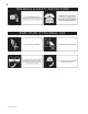
LOG PLACEMENT E TM PHAZER logs, glowing and charcoal embers, exclusive to Napoleon fireplaces, provide a unique and realistic glowing effect that is different in every installation. Take the time to carefully position the embers for a maximum glowing effect. Figures 27 A - H. A #1 LOCATING PINS #3 LOCATING PINS PILOT 5. When pieces #3a and #3b are attached to create log #3, the upper end of log #3 should rest in the groove, on top of log # 2. F 1.
GLOWING EMBERS L36 LOUVRE INSTALLATION For proper ignition, it is very important to that glowing ember s ar e in place embers are place.. Tear the embers into small pieces and place on the ported area of the burner. Care should be taken to shred the embers into thin, small irregular pieces as only the exposed edges of the fibre hairs will glow. The ember material will only glow when exposed to direct flame; however, care should be taken to not block the burner ports.
END DOOR INSTALLATION Ensure that the door is properly clipped onto the steel lip to prevent overheating, glass breakage and / or discolouration of the upper trim. FIGURE 38 FIGURE 37 STEEL LIP DOOR To install the door(s), hook it over the steel lip located above the door opening. Secure with screws along the bottom of the door. Tighten screws snugly. Do not overtighten. FIGURE 39 W415-0320 / D / 01.06.
OPTIONAL BLOWER INSTALLATION THIS BLOWER IS NOT SUITABLE FOR THE 4 SIDED ISLAND INSTALLATION. THERMODISC WIRES TO BLOWER in accordance with local codes. In the absence of local codes, use the current CSA C22.1 CANADIAN ELECTRICAL CODE in Canada or the ANSI/NFPA 70 NATIONAL ELECTRICAL CODE in the United States. Remove the blower from its mounting bracket and attach to the bracket supplied with the fireplace.
OPERATION / MAINTENANCE FOR YOUR SAFETY READ BEFORE LIGHTING: WHAT TO DO IF YOU SMELL GAS: Purge the gas line with a glass door open. Assure that a continuous gas flow is at the burner before re-installing the door. A. This fireplace is equipped with a pilot which must be lit by hand while following these instructions exactly. B. Before operating smell all around the fireplace area for gas and next to the floor because some gas is heavier than air and will settle on the floor. C.
ADJUSTMENTS PILOT BURNER ADJUSTMENT AIR SHUTTER ADJUSTMENT MUST ONLY BE DONE BY A QUALIFIED GAS INSTALLER! Adjust the pilot screw to provide properly sized flame. Turn in a clockwise direction to reduce the gas flow. FIGURE 47 FIGURE 45 VENTURI FIGURE 46 VENTURI ADJUSTMENT MODEL BGNV40 NG 1/4" LP 7/16" Closing the air shutter will cause a more yellow flame, but can lead to carboning. Opening the air shutter will cause a more blue flame, but can cause flame lifting from the burner ports.
REPLACEMENTS Contact your dealer for questions concerning prices and availability of replacement parts. Normally all parts can be ordered through your Napoleon dealer or distributor. * IDENTIFIES ITEMS WHICH ARE NOT ILLUSTRATED. FOR FURTHER INFORMATION, CONTACT YOUR NAPOLEON DEALER. When ordering replacement parts always give the following information: 1. MODEL & SERIAL NUMBER OF FIREPLACE 2. INSTALLATION DATE OF FIREPLACE 3. PART NUMBER 4. DESCRIPTION OF PART 5. FINISH 6.
W415-0320 / D / 01.06.07 * WARNING: This is a fast acting thermocouple. It is an integral safety component. Replace only with a fast acting thermocouple supplied by Wolf Steel Ltd.
ACCESSORIES # PART No.
TROUBLE SHOOTING GUIDE BEFORE ATTEMPTING TO TROUBLESHOOT, PURGE YOUR UNIT AND INITIALLY LIGHT THE PILOT AND THE MAIN BURNER WITH THE GLASS DOOR OPEN. SYMPTOM PROBLEM TEST SOLUTION Main burner goes Pilot flame is not large - turn up pilot flame. out; pilot stays on. enough or not engulfing the - replace pilot assembly. thermopile Thermopile shorting - clean thermopile connection to the valve. Reconnect. - replace thermopile / valve.
SYMPTOM PROBLEM Pilot goes out Gas piping is undersized. while standing; Main burner is in 'OFF' position. TEST SOLUTION - turn on all gas appliances and see if pilot flame flutters, diminishes or extinguishes, especially when main burner ignites. Monitor appliance supply working pressure. - check if supply piping size is to code. Correct all undersized piping. Flames are con- Unit is over-fired or under- - check pressure readings: sistently too large fired.
Date Dealer Name Service Technician Name Service Performed This fireplace must be serviced annually depending on usage. Wolf Steel Fireplace Service History Special Concerns 26 W415-0320 / D / 01.06.
NOTES
NOTES W415-0320 / D / 01.06.