INSTALLER: LEAVE THIS MANUAL WITH THE APPLIANCE. CONSUMER: RETAIN THIS MANUAL FOR FUTURE REFERENCE. INSTALLATION AND OPERATION INSTRUCTIONS CERTIFIED UNDER CANADIAN AND AMERICAN NATIONAL STANDARDS: ANSI Z21.88 • CSA 2.33 FOR VENTED GAS FIREPLACE HEATERS. GDS26N NATURAL GAS GDS26P PROPANE CERTIFIED FOR CANADA AND UNITED STATES USING ANSI / CSA METHODS.
TABLE of CONTENTS 21 21 22-23 PG 3-5 INTRODUCTION Warranty General Instructions General Information Care of Glass and Plated Parts Dimensions 5-15 16-20 Glass Door Installation and Removal Logo Placement Glass Door Replacement Switch Functions Log Placement VENTING Venting Lengths and Air Terminal Locations Vent Installations Typical Vent Installations Special Vent Installations Minimum Air Terminal Location Clearances Venting Application Flow Chart Venting Specifications Vertical Through Existing Ch
NAPOLEON® products are manufactured under the strict Standard of the world recognized ISO 9001 : 2000 Quality Assurance Certificate. NAPOLEON® products are designed with superior components and materials, assembled by trained craftsmen who take great pride in their work. The burner and valve assembly are leak and test-fired at a quality test station.
GENERAL INSTRUCTIONS GENERAL INFORMATION THIS GAS STOVE SHOULD BE INSTALLED AND SERVICED BY A QUALIFIED INSTALLER to conform with local codes. Installation practices vary from region to region and it is important to know the specifics that apply to your area, for example: in Massachusetts State: FOR YOUR SATISFACTION, THIS STOVE HAS BEEN TESTFIRED TO ASSURE ITS OPERATION AND QUALITY! Minimum inlet gas supply pressure is 4.5 inches water column for natural gas and 11 inches water column for propane.
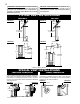
DIMENSIONS FIGURE 1b FIGURE 1a FIGURE 1c 4” DIA. 23 5/8” 7” DIA. 29 /8” 1 35 1/2” 37” GAS LINE ACCESS 18 1/8” ELECTRICAL ACCESS VENTING VENTING LENGTHS AND AIR TERMINAL LOCATIONS Use only Wolf Steel, Simpson Dura-Vent, Selkirk Direct Temp or American Metal Amerivent venting components. Minimum and maximum vent lengths, for both horizontal and vertical installations, and air terminal locations for either system are set out in this manual and must be adhered to.
HORIZONTAL VENT SECTIONS: A minimum clearance of 1" at the bottom and sides and 2" at the top of the vent pipe in all horizontal runs to combustibles is required. Use firestop spacer W010-1313 and shield W585-0240 (supplied). VERTICAL VENT SECTIONS: A minimum of 1" all around the vent pipe on all vertical runs to combustibles is required. Use firestop spacer W0101313 (supplied).
MINIMUM AIR TERMINAL LOCATION CLEARANCES FIGURE 6 W415-0607 / A / 01.18.
W415-0607 / A / 01.18.08 Horizontal run + vertical rise to maximum of 40 feet Vertical rise is equal to or greater than the horizontal run 3.5 times the vertical rise equal to or greater than the horizontal run Horizontal run + vertical rise to maximum of 24.
ELBOW VENT LENGTH VALUES DEFINITIONS for the following symbols used in the venting calculations and examples are: > - greater than > - equal to or greater than < - less than < - equal to or less than HT - total of both horizontal vent lengths (HR) and offsets (HO) in feet HR - combined horizontal vent lengths in feet HO - offset factor: .03(total degrees of offset - 90°*) in feet VT - combined vertical vent lengths in feet feet 0.03 0.45 0.9 1.35 2.7 1° 15° 30° 45° 90°* inches 0.5 6.0 11.0 16.0 32.
TOP EXIT / HORIZONTAL TERMINATION (HT) > (VT) Example 2: Simple venting configuration (only one 90° elbow) V1 = H1 = H2 = HR = HO = HT = HT + VT= FIGURE 9 VT = 6 ft 3 ft 5 ft H1 + H2 = 3 + 5 = 8 ft .03(two 90° elbows - 90°) = .03(180° - 90°) = 2.7 ft HR + HO = 8 + 2.7 = 10.7 ft 10.7 + 6 =16.7 Formula 1: HT < 4.2 VT Formula 2: 10.7 < 25.2 HT + VT < 24.75 feet 16.7 < 24.75 4.2 VT = 4.2 x 6 = 25.2 ft Since both formulas are met, this vent configuration is acceptable.
REAR EXIT / HORIZONTAL TERMINATION Example 4: (HT) < (VT) Simple venting configuration (only two 90° elbows) 90° V2 H3 90° V1 H2 90° FIGURE 12 H1 90° FIGURE 13 See graph to determine the required vertical rise VT for the required horizontal run HT 39 V1 V2 VT H1 H2 H3 HR HO 40 REQUIRED VERTICAL 30 RISE IN FEET 20 VT 10 0 2.5 5 7.5 10 12.5 15 17.5 20 HORIZONTAL VENT RUN PLUS OFFSETS IN FEET HT The shaded area within the lines represents acceptable values for HT and VT .
REAR EXIT / HORIZONTAL TERMINATION Example 5: (HT) > (VT) Simple venting configuration (only two 90° elbows) 90° FIGURE 14 V2 H4 90° H2 V1 45° H3 90° H1 90° FIGURE 15 See graph to determine the required vertical rise VT for the required horizontal run HT 147 REQUIRED VERTICAL RISE IN INCHES VT 150 100 63 = 4 ft = 1.5 ft = V1 + V2 = 4 + 1.5 = 5.5 ft = 2 ft = 1 ft = 1 ft = 1.5 ft = H1 + H2 + H3 + H4 = 2 + 1 + 1 + 1.5 = 5.5 ft = .03(four 90° elbows + one 45° elbow - 90°) = .
TOP OR REAR EXIT VERTICAL TERMINATION (HT) < (VT) Simple venting configurations Example 6: FIGURE 16 FIGURE 17 V3 90° 90° V1 V2 H2 90° H1 90° See graph to determine the required vertical rise VT for the required horizontal run HT. 40 REQUIRED VERTICAL RISE IN FEET VT 30 20 V1 V2 V3 VT H1 H2 HR HO = 5 ft = 6 ft = 10 ft = V1 + V2 + V3 = 5 + 6 + 10 = 21 ft = 8 ft = 2.5 ft = H1 + H2 = 8 + 2.5 = 10.5 ft = .03 (four 90° elbows - 90°) = .03 (90 + 90 + 90 + 90 - 90) = 8.1 ft HT = HR + HO = 10.5 + 8.
VERTICAL THROUGH EXISTING CHIMNEY INSTALLATION This appliance is designed to be attached to a 3" co-linear flexible vent system running the full length of a masonry chimney. The flexible vent pipe accommodates any contours of a masonry chimney, however, it is necessary to keep the flexible vent pipe as straight as possible. The inlet air collar of the termination cap must be connected to the air intake pipe.
REAR EXIT CONVERSION In order to convert the venting configuration from a top exit to a rear exit, remove components as illustrated: When reinstalling in the alternate position: Check gaskets for tears, replace if necessary to ensure a proper seal. FIGURE 19 Outer Top 7” Collar 7” Gasket 4” Collar 7” Cover Plate 4” Gasket 7” Gasket 4” Cover Plate 4” Gasket W415-0607 / A / 01.18.
INSTALLATION WALL AND CEILING PROTECTION For optimum performance, it is recommended that horizontal runs have a minimum 1" rise per foot when using Simpson Dura-Vent, Selkirk Direct Temp, American Metal Amerivent, or Wolf Steel rigid or flexible vent components. For safe and proper operation of the stove, follow the venting instructions exactly. HORIZONTAL INSTALLATION VERTICAL INSTALLATION 1.
STOVE VENT CONNECTION 1. Attach the telescopic sleeve to the last section of 7" rigid vent pipe. Secure 7” RIGID with screws and high temperature sealant W573-0002 (not supplied). VENT PIPE 2. Install the 4" flexible vent pipe to the stove. Secure with 3 screws and flat 4” FLEXIBLE VENT PIPE washers. Seal the joint and screw holes using high temperature sealant W5730007 (not supplied). TELESCOPIC SLEEVE 3.
EXTENDED HORIZONTAL AND CORNER AIR TERMINAL INSTALLATION FIGURE 26 1. Follow the instructions for "Horizontal Air Terminal Installations", items 1 to 3. 2. Continue adding components alternating flexible and rigid vent pipes. Ensure that all 4" flexible vent pipes and elbows have sufficient vent spacers attached and each component is securely fastened to the one prior. Attach the 4" telescopic sleeve to the vent run. Repeat using a 7" telescopic sleeve. Secure and seal as before.
FIGURE 30 GAS INSTALLATION Proceed once the vent installation is complete. SCREWS BAFFLE PLATE FIGURE 31 RESTRICTOR PLATE 1. Remove the front and the door from the stove. 2. Remove the screws securing the baffle plate. Figure 31. Note: The baffle rests on two screws that are attached to the back of the firebox. 3. Using the screws supplied, attach the restrictor plate as show in Figure 31. 4. Replace the baffle. 1.
MINIMUM CLEARANCES TO COMBUSTIBLES SIDE WALL BACK WALL Minimum clearance to combustible construction from stove and vent surfaces: A B C - 2" 5" 2" - 1" to bottom and sides of the vent pipe* 2" to top of the vent pipe* Rear Exit 47 1/2" to ceiling from base of the unit Top Exit 51" to ceiling from base of the unit SIDE WALL BACK WALL * HORIZONTAL VENT SECTIONS: A minimum clearance of 1" at the bottom and sides and 2" at the top of the vent pipe in all horizontal runs to combustibles is required
BLOWER INSTALLATION ELECTRICAL INSTALLATION TO BE DONE BY A QUALIFIED INSTALLER and must be connected and grounded in accordance with local codes. In the absence of local codes, use the current CSA C22.1 CANADIAN ELECTRICAL CODE in Canada or the current ANSI/NFPA 70 NATIONAL ELECTRICAL CODE in the United States. FIGURE 37a 1. Break out the blower and thermal disk knock-outs from the rear panel. Figure 37a This unit is equipped with a three prong grounding plug for your 2.
FINISHING GLASS DOOR INSTALLATION AND REMOVAL 1. Lift the top cast piece off of the unit. 2. Pull handle forward and rotate 90º to unlatch the door. Figure 41a. 3. Lift door straight up to remove. Figure 41b. FIGURE41a 90° FIGURE41b DOOR LOGO PLACEMENT Remove the backing from the logo and position onto the control door as shown. FIGURE 42 1/2” 1/2” LOGO DOOR GLASS REPLACEMENT 1. Place the door frame face down careful not to scratch the paint. 2.
SWITCH FUNCTIONS MAIN BURNER SWITCH NIGHT LIGHTTM SWITCH FAN CONTROL OPTION MAIN BURNER SWITCH This switch turns the Main Burner on and off. NIGHT LIGHTTM SWITCH This switch turns the Night LightTM on and off. FIGURE 44 FAN CONTROL OPTION TOP VIEW If installed this switch will turn on and off the power to the blower and control the fan speed. There is also a thermally activated switch that will only let the blower come on once the unit has reached a comfortable temperature.
WIRING DIAGRAM The main burner on/off switch and Night LightTM switch is located behind lower access panel. For ease of accessibility, optional remote wall switches may be installed in a convenient location for both burner and light operation. The recommended maximum lead length depends on wire size: WIRE SIZE MAX. LENGTH 14 gauge 100 feet 16 gauge 60 feet 18 gauge 40 feet FIGURE 46 Route 2-strand (solid core) wire through the electrical hole located at the bottom left side of the unit.
OPERATION / MAINTENANCE FOR YOUR SAFETY READ BEFORE OPERATING WARNING: IF YOU DO NOT FOLLOW THESE INSTRUCTIONS EXACTLY, A FIRE OR EXPLOSION MAY RESULT CAUSING PROPERTY DAMAGE, PERSONAL INJURY OR LOSS OF LIFE. A. THIS STOVE IS EQUIPPED WITH AN IGNITION DEVICE WHICH AUTOMATICALLY LIGHTS THE PILOT. DO NOT TRY TO LIGHT BY HAND. B. BEFORE OPERATING SMELL ALL AROUND THE STOVE AREA FOR GAS AND NEXT TO THE FLOOR BECAUSE SOME GAS IS HEAVIER THAN AIR AND WILL SETTLE ON THE FLOOR. C.
ADJUSTMENTS PILOT INJECTOR AND ORIFICE REPLACEMENT 1. Turn off the electrical and gas supply to the stove. 2. Remove the cast front, glass viewing door and log set. 3. Remove the 2 securing screws. Slide the burner assembly to the ORIFICE right and lift out. LOCATION 4. Using a deep 9 /16” socket wrench, remove the main burner orifice. A 7/8” back-up wrench must be used on the manifold, located below the housing BURNER to ensure that the ASSEMBLY aluminum tubing does not twist or kink.
REPLACEMENTS Contact your dealer for questions concerning prices and availability of replacement parts. Normally all parts can be ordered through your Napoleon® dealer or distributor. When ordering replacement parts always give the following information: 1. MODEL & SERIAL NUMBER OF STOVE 2. INSTALLATION DATE OF STOVE 3. PART NUMBER 4. DESCRIPTION OF PART 5.
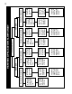
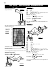
26 32 33 29 31 34 25 27 34 44 28 35 24 AT CA TE NT UT IO IO N NCH AU - HO D T 18 46 34 6 23 8 11 7 17 21 5 16 1 37 3 38 40 41 4 39 W415-0607 / A / 01.18.
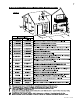
TROUBLE SHOOTING GUIDE BEFORE ATTEMPTING TO TROUBLESHOOT, PURGE YOUR UNIT AND INITIALLY LIGHT THE PILOT AND THE MAIN BURNER WITH THE GLASS DOOR REMOVED. SYMPTOM Pilot will not light. Makes noise with no spark at pilot burner PROBLEM - Module Verify the "S" wire for the sensor and the "I" wire for the ignitor are connected to the correct terminals (not reverse) on the module and pilot assembly. Verify no loose connections, electrical shorts in the wiring or ground out to any metal object.
SYMPTOM Pilot lights Stops sparking / pilot remains lit but burner will not turn on PROBLEM TEST SOLUTION - Wiring / Connection Inspect all wires, ensure good tight connections. Verify that all wiring is installed exactly as specified. - Wiring harness Inspect the wiring harness, and verify the harness is tightly connected to the module. Verify that you have 7 wires and they are connected in the right order.
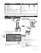
Date Dealer Name Service Technician Name Service Performed This fireplace must be serviced annually depending on usage. Wolf Steel Fireplace Service History Special Concerns 31 W415-0607 / A / 01.18.
NOTES W415-0607 / A / 01.18.