INSTALLER: THESE INSTRUCTIONS MUST BE CONVEYED TO AND REMAIN WITH THE HOMEOWNER. CERTIFIED UNDER CANADIAN AND AMERICAN NATIONAL STANDARDS, CSA 2.33, ANSI Z21.
TABLE of CONTENTS PG 2-4 INTRODUCTION PG 21 Warranty General Instructions General Information Care of Glass & Plated Parts 5 - 12 VENTING Venting Lengths Air Terminal Locations Typical Vent Installations Special Vent Installations OPTIONAL BLOWER INSTALLATION 22 OPTIONAL FAN INSTALLATION / GD36 THERMOSTATIC SENSOR CONTROL 23 OPERATION / MAINTENANCE Operating Instructions Maintenance 24 ADJUSTMENTS Pilot Burner Adjustment Venturi Adjustment 13 - 18 INSTALLATION Wall and Ceiling Protection Using
NAPOLEON products are manufactured under the strict Standard of the world recognized ISO 9001 : 2000 Quality Assurance Certificate. NAPOLEON products are designed with superior components and materials, assembled by trained craftsmen who take great pride in their work. The burner and valve assembly are leak and test-fired at a quality test station.
GENERAL INSTRUCTIONS THIS GAS FIREPLACE SHOULD BE INSTALLED AND SERVICED BY A QUALIFIED INSTALLER to conform with local codes. In absence of local codes, install the BGD42 to the current National Fuel Gas Code, ANSI Z223.1, or the current CAN/CGA B149, Installation Codes.
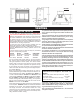
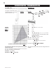
FIGURE 1 VENTING VENTING LENGTHS Use only Wolf Steel, Simpson Dura-Vent, Selkirk Direct Temp or American Metal Amerivent venting components. Minimum and maximum vent lengths, for both horizontal and vertical installations, and air terminal locations for either system are set out in this manual and must be adhered to. For Simpson Dura-Vent, Selkirk Direct Temp and American Metal Amerivent, follow the installation procedure provided with the venting components.
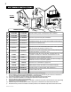
AIR TERMINAL INSTALLATIONS FIGURE 2 INSTALLATIONS CANADIAN U.S.A. A 12 INCHES 12 INCHES B 12 INCHES 9 INCHES C 12 INCHES* 12 INCHES* Clearance to permanently closed windows. D 32 INCHES** 32 INCHES** Vertical clearance to ventilated soffit located above the terminal within a horizontal distance of 2 feet from the centerline of the terminal. E 32 INCHES** 32 INCHES** Clearance to unventilated soffit.
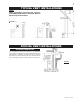
TYPICAL VENT INSTALLATIONS NOTE: When terminating vertically, the restrictor plate W500-0205 must be installed. Refer to Restricting Vertical Vents. FIGURES 3 a-c SPECIAL VENT INSTALLATIONS PERISCOPE TERMINATION Use the GD401 periscope kit to locate the air termination above grade. The periscope must be installed so that when final grading is completed, the bottom air slot is located a minimum of 12 inches above grade. The maximum allowable vent length depends on the fireplace, as illustrated.
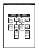
VENTING APPLICATION FLOW CHART HORIZONTAL TERMINATION vertical rise is equal to or greater than the horizontal run horizontal run + vertical rise to maximum of 40 feet vertical rise is less than horizontal run horizontal run + vertical rise to maximum of 24.75 feet 4.2 times the vertical rise equal to or greater than the horizontal run W415-0381 / E / 02.09.
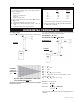
DEFINITIONS for the following symbols used in the venting calculations and examples are: > - greater than > - equal to or greater than < - less than < - equal to or less than HT - total of both horizontal vent lengths (HR) and offsets (HO) in feet HR - combined horizontal vent lengths in feet HO - offset factor: .03(total degrees of offset - 135°*) in feet VT - combined vertical vent lengths in feet ELBOW VENT LENGTH VALUES feet 0.03 0.45 0.9 1.35 2.7 1° 15° 30° 45°* 90°* inches 0.5 6.0 11.0 16.0 32.
HORIZONTAL TERMINATION when (HT) > (VT) Simple venting configuration (only one 45º and 90° elbow) See graph to determine the required vertical rise VT for the required horizontal run HT. FIGURE 7 Example 2: 90° FIGURE 8 45° H3 H1 H2 H4 V2 90° V1 REQUIRED VERTICAL RISE IN INCHES (VT) 90° = 4 ft = 1.5 ft = V1 + V2 = 4 ft + 1.5 ft = 5.5 ft = 2 ft = 1 ft = 1 ft = 1.5 ft = H1 + H2 + H3 + H4 = 2 + 1 + 1 + 1. 5 = 5.5 ft = .03(one 45º elbow + three 90º elbow -135º) =.03(315-135)=5.
VERTICAL TERMINATION when (HT) < (VT) Example 3: Simple venting configurations FIGURE 9 V2 FIGURE10 90° 45° H2 V1 90° 45° H1 90° See graph to determine the required vertical rise VT for the required horizontal run HT. V1 V2 = 5 ft = 10 ft = V1 + V2 = 5 + 10 = 15 ft = 3 ft = 2.5 ft = H1 + H2 = 3 + 2.5 = 5.5 ft = .03(one 45º elbow + three 90º elbows - 135º) = .03(45+90+90+90-135)=5.4 HT = HR + HO = 5.5 + 5.4 = 10.9 ft HT + VT = 10.9 + 15 = 25.
VERTICAL TERMINATION when (HT) > (VT) Simple venting configurations V1 V2 = 1 ft = 1.5 ft = V1 + V2 = 1 + 1.5 = 2.5 ft = 6 ft = 2 ft = H1 + H2 = 6 + 2 = 8 ft = .03(one 45º elbow + three 90º elbow - 135º) = .03(45 + 90 + 90 + 90 - 135) = 5.4 ft HT = HR + HO = 8 + 5.4 = 13.4 ft HT + VT = 13.4 + 2.5 = 15.9 ft VT H1 H2 HR HO FIGURE 11 Formula 1: See graph to determine the required vertical rise VT for the required horizontal run HT. REQUIRED VERTICAL RISE IN FEET (VT) HT < 3VT 3VT = 3 x 2.5 = 7.
INSTALLATION WALL AND CEILING PROTECTION FOR SAFE AND PROPER OPERATION OF THE FIREPLACE, FOLLOW THE VENTING INSTRUCTIONS EXACTLY. NOTE: Only a clearance to combustibles of 1" all around the vent pipe is required. HORIZONTAL INSTALLATION This application occurs when venting through an exterior wall. Having determined the air terminal location, cut and frame a hole in an exterior wall with a minimum opening as required. See Note above.
USING FLEXIBLE VENT COMPONENTS Use only approved aluminum flexible liner kits marked: "Wolf Steel Approved Venting" as identified by the stamp only on the 7” outer liner. HORIZONTAL AIR TERMINAL INSTALLATION A VENT SHIELD MUST BE USED IF THE WALL TERMINAL IS INSTALLED ON COMBUSTIBLE, EXTERIOR SURFACES. 1. Cut or frame a hole in an exterior wall with a minimum round or square opening of 10½ inches. Secure the firestop spacer over the opening to the interior wall. 2.
5. Remove nails from the shingles, above and to the sides of the chimney. Place the flashing over the air terminal connector leaving a min. 3/4” of the air terminal connector showing above the top of the flashing. Slide the flashing underneath the sides and upper edge of the shingles. Ensure that the air terminal connector is properly centred within the flashing, giving a 3/4” margin all around. Fasten to the roof. Do not nail through the lower portion of the flashing.
VERTICAL VENTING INSTALLATION RESTRICTING VERTICAL VENTS 1. Move the fireplace into position. 2. Fasten the roof support to the roof using the screws provided. FIGURE 21. The roof support is optional. In this case the venting is to be adequately supported using either an alternate method suitable to the authority having jurisdiction or the optional roof support. 3. Apply high temperature sealant to the outer edge of the inner sleeve of the air terminal.
FIGURETOP 29 OF THEin place. Use #10 hex head screws, inserted through the ESTRICTORFIREBOX PLATE holes in the base to secure. It is recommended that the fireplace be secured in all installations. Always turn off the pilot and the fuel supply at the source, prior to moving the mobile home. After moving the mobile home and prior to lighting the fireplace, ensure that the logs are positioned correctly.
NAILING TAB INSTALLATION FIGURES 35a-c CORNER 1) Attach the nailing tabs to the corner posts using the 2 sheet metal screws supplied. Secure through the centre of the top and bottom slots in the nailing tab and then through the existing holes in the corner posts. If there are no existing holes, follow these instructions: POST NAILING TAB TOP SLOT NAILING TAB Position the nailing tab so that the front face is offset with the front edge of the corner post (approx. ½").
FINISHING GDL42 LOUVRE INSTALLATION PHAZERTM logs and glowing embers, exclusive to NapoUPPERLOUVRE leon Fireplaces, provide a unique and realistic glowing effect that is different SLOTin every installation. Take the time to carefully position the glowing embers for a maximum glowing effect. Log colours may vary. During the initial use of the fireplace, the colours will become more uniform as colour a DOOR LATCH pigments burn in during the heat activated curing process.
GRATE INSTALLATION The grate for this fireplace has been removed for shipping purposes. The grate must be installed before the logs are installed. Remove the packaging from the grate and install onto the two pins as illustrated. LOG PLACEMENT the front row of ports covering all of the burner area in front of the small logs (#2 & #3). Care should be taken to shred the embers into thin, small irregular pieces as only the exposed edges of the fibre hairs will glow.
CHARCOAL EMBERS CHARCOAL LUMPS bracket allow ease of adjustment when attaching the blower. firebox base. Slide the vibration reducing pad (A) into the clip (C) and up VERMICULITE For a quiet running blower, do not allow the assembly to sit on the OPTIONAL BLOWER INSTALLATION against the threaded stud (B) at the other end. The blower must be able to be positioned entirely onto the pad. Tilt the blower onto its side. Slide it past the FIGURE 41 controls and into the clip (C).
OPTIONAL FAN INSTALLATION Position the vibration reducing pad into the clip and onto the threaded stud at the other end, piercing a hole into the pad. The fan assembly must be able to be positioned entirely onto the pad. Slide the fan assembly past the controls and into the clip. Secure using the lock washer and nut provided. FIGURE 47 Plug the harness cord into the receptacle.
OPERATION / MAINTENANCE OPERATING INSTRUCTIONS than air and will settle on the floor C. Use only your hand to turn the gas control knob. Never use tools. If the knob will not turn by hand, do not try to repair it. Call a qualified service technician. Force or attempted repair may result in a fire or explosion. FOR YOUR SAFETY READ BEFORE LIGHTING: • Do not touch any electric switch; do not use any phone in your building. • Immediately call your gas supplier from a neighbour's phone.
ADJUSTMENTS PILOT BURNER ADJUSTMENT Air shutters have been factory set open according to the chart below: These settings are for the maximum horizontal vent run.Adjustment FIGURE 51 may be required depending on fuel type, vent configuration and altitude. Closing the air shutter will cause a more yellow flame, but can lead to carboning. Opening the air shutter will cause a more blue flame, but can cause flame lifting from the burner FIGURE 52 immediately; allow ports.
REPLACEMENTS Contact your dealer for questions concerning prices and availability of replacement parts. Normally all parts can be ordered through your Napoleon dealer or distributor. FOR WARRANTY REPLACEMENT PARTS, A PHOTOCOPY OF THE ORIGINAL INVOICE WILL BE REQUIRED TO HONOUR THE CLAIM. * IDENTIFIES ITEMS WHICH ARE NOT ILLUSTRATED. FOR FURTHER INFORMATION, CONTACT YOUR NAPOLEON DEALER.
W415-0381 / E / 02.09.
TROUBLE SHOOTING GUIDE BEFORE ATTEMPTING TO TROUBLESHOOT, PURGE YOUR UNIT AND INITIALLY LIGHT THE PILOT AND THE MAIN BURNER WITH THE GLASS DOOR REMOVED. SYMPTOM PROBLEM TEST SOLUTION Main burner goes Pilot flame is not large - turn up pilot flame. out; pilot stays on. enough or not engulfing the - replace pilot assembly. thermopile Thermopile shorting - clean thermopile connection to the valve. Reconnect. - replace thermopile / valve.
SYMPTOM PROBLEM Pilot goes out Gas piping is undersized. while standing; Main burner is in 'OFF' position. TEST SOLUTION - turn on all gas appliances and see if pilot flame flutters, diminishes or extinguishes, especially when main burner ignites. Monitor appliance supply working pressure. - check if supply piping size is to code. Correct all undersized piping. Flames are con- Unit is over-fired or under- - check pressure readings: sistently too large fired.