INSTALLER: THESE INSTRUCTIONS MUST BE CONVEYED TO AND REMAIN WITH THE HOMEOWNER. CERTIFIED UNDER CANADIAN AND AMERICAN NATIONAL STANDARDS, CSA 2.33, ANSI Z21.
TABLE of CONTENTS PG2-5 5-10 11-15 16-19 INTRODUCTION Warranty Dimensions General Instructions General Information Care of Glass & Plated Parts 20 BLOWER INSTALLATION THERMODISC REPLACEMENT 21-22 OPERATION / MAINTENANCE 22 VENTING Vent lengths Venting Specifications Air Terminal Locations INSTALLATION/FRAMING Wall & Ceiling Protection Using Flexible Vent Components Fireplace Vent Connection Using Rigid Vent Components Restricting Vertical Vents Gas Installation Mobile Home Installation Framin
NAPOLEON gas fireplaces are manufactured under the strict Standard of the world recognized ISO 9001 : 2000 Quality Assurance Certificate. NAPOLEON products are designed with superior components and materials, assembled by trained craftsmen who take great pride in their work. The burner and valve assembly are leak and test-fired at a quality test station.
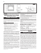
FIGURE 1 WARNING: The door for this fireplace is sold separately. The door must be installed and closed before operation begins. Refer to "DOOR INSTALLATION" under the "FINISHING" Section for details. Purge all gas lines with the glass door of the fireplace open. Assure that a continuous gas flow is at the burner before closing the door. GENERAL INSTRUCTIONS Eight (8") inches is the minimum bend radius allowed for the 7" diameter flexible air liner.
This fireplace may be installed in an aftermarket permanently located, manufactured (mobile) home, where not pr ohibited b y local codes prohibited by codes.. This fireplace is only for use with the type of gas indicated te his ffir ir eplace is not con ver tib le ffor on the rra ating pla or use tible plate te.. T This ire conv ertib with other gases, unless a certified kit is used. No external electricity (110 volts or 24 volts) is required for the gas system operation.
DEFINITIONS for the following symbols used in the venting calculations and examples are: > - greater than > - equal to or greater than < - less than < - equal to or less than HT - total of both horizontal vent lengths (HR) and offsets (HO) in feet HR - combined horizontal vent lengths in feet HO - offset factor: .03(total degrees of offset - 90°*) in feet VT - combined vertical vent lengths in feet ELBOW VENT LENGTH VALUES feet 0.03 0.45 0.9 1.35 2.7 1° 15° 30° 45° 90°* inches 0.5 6.0 11.0 16.0 32.
TOP EXIT / HORIZONTAL TERMINATION when (HT) > (VT) Simple venting configuration (only one 90° elbow) Example 3: H1 FIGURE 6 See graph to determine the required vertical rise VT for the required horizontal run HT. V1 VT HORIZONTAL VENT RUN PLUS OFFSET IN FEET HT The shaded area within the lines represents acceptable values for HT and VT . For vent configurations requiring more than one 90° elbow the following formulas apply: H2 H4 H3 V1 V2 VT H1 H2 H3 H4 HR HO HT HT + VT = 4 ft = 1.
VERTICAL TERMINATION when (HT) < (VT) Simple venting configurations FIGURE 9 40 REQUIRED VERTICAL RISE IN FEET 30 VT 20 10 3 0 5 10 15 2 0 HORIZONTAL VENT RUN PLUS OFFSET IN FEET H T The shaded area within the lines represents acceptable values for H T and V T . See graph to determine the required vertical rise VT for the required horizontal run HT.
VERTICAL TERMINATION when (HT) > (VT) Simple venting configurations For vent configurations requiring more than two 90° elbow the following formulas apply: Formula 1: H T < 3VT Formula 2: HT + VT < 40 feet FIGURE 1 0 Example 7: 90° V1 90° H1 V2 H2 90° V3 90° See graph to determine the required vertical rise VT for the required horizontal run HT.
AIR TERMINAL INSTALLATIONS FIGURE 12 INSTALLATIONS CANADIAN U.S.A. A 12 INCHES 12 INCHES Clearance above grade, veranda porch, deck or balcony. B 12 INCHES 9 INCHES Clearance to windows or doors that open. C 12 INCHES* 12 INCHES* D 18 INCHES** Vertical clearance to ventilated soffit located above the terminal within 18 INCHES** a horizontal distance of 2 feet from the centerline of the terminal. E 12 INCHES** 12 INCHES** Clearance to unventilated soffit.
INSTALLATION WALL AND CEILING PROTECTION For optimum performance it is recommended that all horizontal runs have a minimum ¼ inch rise per foot using flexible venting. For safe and proper operation of the fireplace, follow the venting instructions exactly. VERTICAL INSTALLATION This application occurs when venting through a FIGURE 15 roof.
USING FLEXIBLE VENT COMPONENTS Use only approved aluminum flexible liner kits marked " Wolf Steel Approved Venting" as identified by the stamp only on the 7" outer liner. For optimum performance it is recommended that all horizontal runs have a minimum ¼ inch rise per foot using flexible venting. For safe and proper operation of the fireplace, follow the venting instructions exactly.
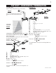
Spacers are attached to the 4" inner flex liner at predetermined intervals to maintain a 1-1/4" air gap to the 7" outer liner. These spacers must not be removed. 7. If more liner needs to be used to reach the fireplace, couple them together as illustrated in FIGURE 13. The vent system must be supported approximately every 3 feet for both vertical and horizontal runs. Use Wolf Steel support ring assembly W010-0370 or equivalent noncombustible strapping to maintain a clearance to combustibles of 1".
8. Continue adding rigid venting sections, sealing and securing as above. Attach a 4" collapsed telescopic pipe to the last section of rigid piping. Secure with screws and seal. Repeat using a 7" telescopic pipe. 9. Run a bead of high temperature sealant around the outside of the 4" elbow. Pull the adjustable pipe a minimum 2" onto the elbow. Secure with 3 screws. Repeat with the 7" telescopic pipe. 10. In the attic, slide the vent pipe collar down to cover up the open end of the shield and tighten.
EXAMPLE A - NON-COMBUSTIBLE MATERIAL It is best to frame your fireplace after it is positioned and the vent system is installed. Use 2x4's and frame to local building codes. To install the fireplace face flush with the finished wall, position the framework to accomodate the thickness of the finished wall.
FINISHING DOOR INSTALLATION GDLV LOUVRE INSTALLATION Loosely thread a screw provided with the door kit into the top hole on the left side of the firebox. Hang the door by the hinge onto the screw. Insert the remaining 4 screws and tighten. IMPORTANT: Ensure screws are driven in straight or the hole thread may be damaged. FIGURE 38 DOOR CLOSING AND OPENING Open the valve control door. Hook the top and bottom door latches, located at the right side of the door into the corresponding slots in the door.
L38 LOUVRE INSTALLATION FIGURE 43 a-c LOG SHIPPING BRACKET FIGURE 45 A SCREW LOG SHIPPING BRACKET Before installing the logs, you must first remove the log shipping bracket. Loosen the securing screw indicated. Slide the bracket to the right and lift up to remove. B DECORATIVE PANELS This fireplace does not include decorative brick panels, however, panels are required. You now have the option of choosing 1 of 4 panel kits SOLD SEPARATELY. (See Accessories).
LOG PLACEMENT PHAZER logs, exclusive to Napoleon Fireplaces, provide a unique and realistic glowing effect that is different in every installation. FIGURES 46a-e TM 4 1 4. Place log #4, with the charred branch pointed inward. Locate the pins into the holes in log#1 and log#2, this will hold the rear log in position. CHARCOAL STRIPS 1. Centre the two charcoal strips, as shown, along the inside front edge of the firebox.
ACCENT LITE REPLACEMENT IN LINE SWITCH Your Napoleon STARfire comes equipped with our “Accent Lite”. The light has been pre-wired and can be controlled from the switch on the control panel. The FIRE LOG ACCENT LIGHT is provided with a manual "inline" switch to turn the light on and off. There are alternate methods of operating the light. It is recommended that the ACCENT LITE be in the off position when the fireplace is on. An example of one method would be to "hard-wire" a wall switch.
BLOWER INSTALLATION BLOWER SYSTEM The Napoleon STARfire comes equipped with a blower, a heat sensor, variable on/off speed control and a power cord. The blower is thermally activated, so when it is turned on, it will automatically start approximately 15 minutes after lighting the fireplace and will run for approximately 30 minutes after the fireplace has been turned off. Use of the fan increases the output of heat.
OPERATION / MAINTENANCE OPERATING INSTRUCTIONS When lit for the first time, the fireplace will emit a slight odour for a few hours. This is a normal temporary condition caused by the curing of the logs and the "burn-in" of internal paints and lubricants used in the manufacturing process and will not occur again. Simply open a window to sufficiently ventilate the room.
MAINTENANCE TURN OFF THE GAS AND ELECTRICAL POWER BEFORE SERVICING THE FIREPLACE. CAUTION: Label all wires prior to disconnection when servicing controls. Wiring errors can cause improper and dangerous operation. Verify proper operation after servicing. This fireplace and its venting system should be inspected before use and at least annually by a qualified service person. The fireplace area must be kept clear and free of combustible materials, gasoline or other flammable vapours and liquids.
REPLACEMENTS Contact your dealer for questions concerning prices and availability of replacement parts. Normally all parts can be ordered through your Napoleon dealer or distributor. When ordering replacement parts always give the following information: FOR WARRANTY REPL ACEMENT PAR TS, A PHO TOCOPY OF THE REPLA ARTS PHOT 1. 2. 3. 4. 5. ORIGINAL INVOICE WILL BE REQUIRED TO HONOUR THE CLAIM.
W415-0434 / C / 03.24.05 * WARNING: This is a fast acting thermocouple. It is an integral safety component. Replace only with a fast acting thermocouple supplied by Wolf Steel Ltd.
TROUBLE SHOOTING GUIDE BEFORE ATTEMPTING TO TROUBLESHOOT, PURGE YOUR UNIT AND INITIALLY LIGHT THE PILOT AND THE MAIN BURNER WITH THE GLASS DOOR OPEN. SYMPTOM PROBLEM Main burner flame Blockage in vent. is a blue, lazy, transparent flame. Incorrect installation. TEST SOLUTION - remove blockage. In really cold conditions, ice buildup may occur on the terminal and should be removed as required. - refer to Figure 13 to ensure correct location of storm collars.
SYMPTOM PROBLEM Pilot burning; no Themostat or switch is degas to main fective. burner; gas knob Wall switch wiring is defecis on 'HI'; wall tive. switch / thermostat is on. Main burner orifice is plugged. Faulty valve. TEST SOLUTION - connect a jumper wire across the wall switch terminals; if main burner lights, replace switch / thermostat. - disconnect switch wires &connect a jumper wire across terminals 1 & 3; if the main burner lights, check the wires for defects and / or replace wires.
Date Dealer Name Service Technician Name Service Performed This fireplace must be serviced annually depending on usage. Wolf Steel Fireplace Service History Special Concerns 27 W415-0434 / C / 03.24.
NOTES W415-0434 / C / 03.24.