W415-0447 / B / 05.24.05 W415-0447 / B / 05.24.
WARNINGS & SAFETY PRECAUTIONS WHAT TO DO IF YOU SMELL GAS W415-0447 / B / 05.24.
TABLE of CONTENTS PG2-6 INTRODUCTION 20 Warnings and Safety Precautions Warranty Dimensions General Instructions General Information Care of Glass & Plated Parts 6-11 21 REMOTE AND VALVE ACCESS Remote Removal Valve Removal 22-24 OPERATION / MAINTENANCE Fireplace Operation Hand Held Remote Operation Operating Instructions Maintenance VENTING Vent lengths Venting Specifications Air Terminal Locations 12-17 BLOWER REPLACEMENT INSTALLATION/FRAMING Wall & Ceiling Protection Using Flexible Vent Comp
NAPOLEON gas fireplaces are manufactured under the strict Standard of the world recognized ISO 9001 : 2000 Quality Assurance Certificate. NAPOLEON products are designed with superior components and materials, assembled by trained craftsmen who take great pride in their work. The burner and valve assembly are leak and test-fired at a quality test station.
FIGURE 1 GENERAL INSTRUCTIONS THIS GAS FIREPLACE SHOULD BE INSTALLED AND SERVICED BY A QUALIFIED INSTALLER to conform with local codes. Installation practices vary from region to region and it is important to know the specifics that apply to your area, for example: in Massachusetts State: • The fireplace damper must be removed or welded in the open position prior to installation of a fireplace insert or gas log. • The appliance off valve must be a “T” handle gas cock.
This fireplace may be installed in an aftermarket permanently located, manufactured (mobile) home, where not prohibited by local codes. This fireplace is only for use with the type of gas indicated on the rating plate. This fireplace is not convertible for use with other gases, unless a certified kit is used. No external electricity (110 volts or 24 volts) is required for the gas system operation. Expansion / contraction nosies during heating up and cooling down cycles are normal and are to be expected.
DEFINITIONS for the following symbols used in the venting calculations and examples are: > - greater than > - equal to or greater than < - less than < - equal to or less than HT - total of both horizontal vent lengths (HR) and offsets (HO) in feet HR - combined horizontal vent lengths in feet HO - offset factor: .03(total degrees of offset - 90°*) in feet VT - combined vertical vent lengths in feet ELBOW VENT LENGTH VALUES 1° 15° 30° 45° 90°* feet 0.03 0.45 0.9 1.35 2.7 inches 0.5 6.0 11.0 16.0 32.
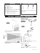
TOP EXIT / HORIZONTAL TERMINATION when (HT) > (VT) Simple venting configuration (only one 90° elbow) Example 3: 90° H4 H1 FIGURE 6 H2 See graph to determine the required vertical rise VT for the required horizontal run HT. V1 90° V2 H3 FIGURE 8 V1 V2 VT H1 H2 H3 H4 HR HO HT HT + VT REQUIRED VERTICAL RISE IN INCHES VT HORIZONTAL VENT RUN PLUS OFFSET IN FEET HT The shaded area within the lines represents acceptable values for HT and VT .
TOP EXIT VERTICAL TERMINATION when (HT) < (VT) Simple venting configurations FIGURE 9 REQUIRED VERTICAL RISE IN FEET VT HORIZONTAL VENT RUN PLUS OFFSET IN FEET HT The shaded area within the lines represents acceptable values for HT and VT . See graph to determine the required vertical rise VT for the required horizontal run HT.
TOP VERTICAL TERMINATION when (HT) > (VT) Simple venting configurations For vent configurations requiring more than two 90° elbow (top exit) or one 90° elbow (rear exit), the following formulas apply: FIGURE 10 Formula 1: HT < 3VT Formula 2: HT + VT < 40 feet Example 7: 90° V1 90° H1 V2 H2 90° See graph to determine the required vertical rise VT for the required horizontal run HT.
AIR TERMINAL INSTALLATIONS FIGURE 12 INSTALLATIONS CANADIAN U.S.A. A 12 INCHES 12 INCHES Clearance above grade, veranda porch, deck or balcony. B 12 INCHES 9 INCHES Clearance to windows or doors that open. C 12 INCHES* 12 INCHES* Clearance to permanently closed windows. D 18 INCHES** 18 INCHES** Vertical clearance to ventilated soffit located above the terminal within a horizontal distance of 2 feet from the centerline of the terminal.
INSTALLATION WALL AND CEILING PROTECTION FOR SAFE AND PROPER OPERATION OF THE FIREPLACE, FOLLOW THE VENTING INSTRUCTIONS EXACTLY. A 2” CLEARANCE IS REQUIRED AROUND THE VENT PIPE. HORIZONTAL INSTALLATION This application occurs when FIGURE 13 venting through an exterior wall. Having determined the air 13" ROUND OR terminal location, cut and frame 12.500" SQUARE HOLE a hole in an exterior wall.
USING FLEXIBLE VENT COMPONENTS Use only approved aluminum flexible liner kits marked: "Wolf Steel Approved Venting" as identified by the stamp only on the 8” outer liner. HORIZONTAL AIR TERMINAL INSTALLATION 1. Cut or frame a hole in an exterior wall with a minimum round or square opening of 121/2" W x 121/2" H. Secure the firestop spacer over the opening to the interior wall. Secure the terminal to the terminal extension plate (see figure 19). 2.
5. Remove nails from the shingles, above and to the sides of the chimney. Place the flashing over the air terminal and slide it underneath the sides and upper edge of the shingles. Ensure that the air terminal is properly centred within the flashing, giving a 3/4" margin all around. Fasten to the roof. Do not nail through the lower portion of the flashing. Make weather-tight by sealing with caulking. Where possible, cover the sides and top edges of the flashing with roofing material. 6.
VERTICAL VENTING INSTALLATION 1. Move the fireplace into position. 2. Fasten the roof support to the roof using the screws provided. The roof support is optional. In this case the venting is to be adequately supported using either an alternate method suitable to the authority having jurisdiction or the optional roof support. 3. Apply high temperature sealant (W573-0007 not provided) to the outer edge of the inner sleeve of the air terminal.
CLEARANCE TO COMBUSTIBLES FRAMING The Madison can be installed with either an arched opening (FK80-A) or a rectangular opening (FK80-R) using one of the above kits. The framing kits serve two purposes. They are necessary if optional doors (DK80) are to be installed. Secondly, they act as a reference when finishing to the fireplace opening. The FK80 is designed to accomodate 1/2” to 1 1/2” finishing material. They are adjustable to ensure doors open fully .
MANTLE CLEARANCES Combustible mantle clearance can vary according to the mantle depth. Use the graph to help evaluate the clearance needed. FIGURE 34 ELECTRICAL CONNECTION Do NOT use the fireplace if any part has been under water. Call a qualified service technician IMMEDIATELY to have the fireplace inspected for damage to the electrical circuit. If access to the control area is necessary BEFORE INSTALLATION, remove the access panel. The access panel must be re-installed before operating the unit.
FINISHING FIGURE 38 DOOR REMOVAL FIGURE 36 Before the glass door can be removed, the control doors must be removed and the hearth strip and screen assembly must be removed. FIGURE 37 The glass door is secured to the top front edge of the firebox. Pull the handle of the latch forward, then lift the hook out from the slot in the door frame to release the top of the door. Lift the door out from the retainer along the bottom of the door using the top and bottom handles.
Decorative brick panels must be installed before the logs. See installation instructions supplied with the panel kit. LOG PLACEMENT PHAZER logs, exclusive to Napoleon Fireplaces, provide a unique and realistic glowing effect that is different in every installation. The madison logs are fuel specific. Do not interchange. Refer to the replacement parts list. TM 4 FIGURE 40a-f 1 4. Place log #4, with the charred branch pointed inward.
LAMP REPLACEMENT 1. Turn off the power to the unit. 2. Turn off the gas valve. 3. Remove the door and logs. FIGURE 42 FIGURE 41 4. Loosen the lense retainer screws and pivot the retainers out of the way. 5. Using a small flat screwdriver, gently lift the orange lense from the housing. 6. Slide the defective bulb to either side until the opposite end is disengaged. Remove the bulb lifting the disengaged end. 7. Replace with a 75 watt halogen lamp (E-11 BASE).
REMOTE AND VALVE ACCESS INNER ACCESS DOOR The control area can be accessed either through the control door or through the access door inside the firebox. Follow the door removal instructions. Remove the right side panel. Remove the four screws from the access door. Note: A new gasket will be required, when re-installing the door (see replacement parts). FIGURE 47 CONTROL DOOR 1. Remove hearth strip. the 2. Open the right control door. 3. Remove the switch plate by pulling on the left side. 4.
OPERATION / MAINTENANCE FIREPLACE OPERATION To operate the gas fireplace, the pilot needs to be running and the gas valve turned to the on position. You can run the fireplace on manual or remote. When operating the main burner on manual without power, the fireplace will operate on low input only. Turn the main power switch to FIGURE 49 manual to operate the gas features of the fireplace in the event of a power failure.
To restore button function temporarily, press the Up and Down buttons in the following sequence: up-down-down-up-down. If no button is pressed within 2 minutes, the transmitter will return to the Child-Proof mode. IN THE EVENT OF A POWER FAILURE To operate the fireplace manually in the event of a power/ battery failure, the main power switch located in the fireplace, may be switched to the manual position. Once power has been restored, it will be necessary to reset the remote.
MAINTENANCE TURN OFF THE GAS AND ELECTRICAL POWER BEFORE SERVICING THE FIREPLACE. CAUTION: Label all wires prior to disconnection when servicing controls. Wiring errors can cause improper and dangerous operation. Verify proper operation after servicing. This fireplace and its venting system should be inspected before use and at least annually by a qualified service person. The fireplace area must be kept clear and free of combustible materials, gasoline or other flammable vapours and liquids.
REPLACEMENTS Contact your dealer for questions concerning prices and availability of replacement parts. Normally all parts can be ordered through your Napoleon dealer or distributor. When ordering replacement parts always give the following information: FOR WARRANTY REPLACEMENT PARTS, A PHOTOCOPY OF THE ORIGINAL INVOICE WILL BE REQUIRED TO HONOUR THE CLAIM. REPLACEMENT PARTS # PART NO.
W415-0447 / B / 05.24.05 * WARNING: This is a fast acting thermocouple. It is an integral safety component. Replace only with a fast acting thermocouple supplied by Wolf Steel Ltd.
TROUBLE SHOOTING GUIDE BEFORE ATTEMPTING TO TROUBLESHOOT, PURGE YOUR UNIT AND INITIALLY LIGHT THE PILOT AND THE MAIN BURNER WITH THE GLASS DOOR OPEN. SYMPTOM PROBLEM Main burner flame Blockage in vent. is a blue, lazy, transparent flame. Incorrect installation. TEST SOLUTION - remove blockage. In really cold conditions, ice buildup may occur on the terminal and should be removed as required. - refer to Figure 13 to ensure correct location of storm collars.
SYMPTOM PROBLEM Pilot burning; no Themostat or switch is defecgas to main burner; tive. gas knob is on 'HI'; Wall switch wiring is defecwall switch / ther- tive. mostat is on. TEST SOLUTION - connect a jumper wire across the wall switch terminals; if main burner lights, replace switch / thermostat. - disconnect switch wires &connect a jumper wire across terminals 1 & 3; if the main burner lights, check the wires for defects and / or replace wires. Main burner orifice is plugged.