
User's Manual

13
W415-0447 / B / 05.24.05
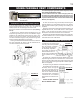
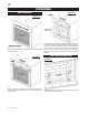
FIGURE 19
4. Insert the liners through the firestop maintaining the
required clearance to combustibles. Secure to the exterior
wall and make weather tight by sealing with caulking (not
supplied).
5. Apply a heavy bead of the high temperature sealant, not
supplied with the unit, to the inside of the 5" liner approxi-
mately 1" from the end. Slip the liner a minimum of 2" over
the fireplace vent collar and secure with 3 #8 screws.
6. Using the 8" diameter flexible aluminium liner, apply seal-
ant, slide a minimum of 2" over the fireplace combustion air
collar and secure with 3 #8 screws.
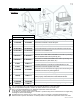
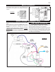
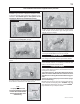
1. Fasten the roof support to the
roof using the screws provided.
The roof support is optional.
In this case the venting is to
be adequately supported
using either an alternate
method suitable to the au-
thority having jurisdiction
or the optional roof sup-
port.
2. Stretch the 5" diameter aluminium flexible liner to the
required length. Slip the liner a minimum of 2" over the inner
sleeve of the air terminal and secure with 3 #8 screws. Seal
using a heavy bead of the high temperature sealant (W573-
0007 not supplied).
3. Repeat using 8" diameter aluminium flexible liner.
4. Thread the air terminal pipe
assembly down through the
roof. The air terminal must be
located vertically and plumb. At-
tach the air terminal assembly
to the roof support, ensuring that
a minimum 16" of air terminal
will penetrate the roof when fas-
tened.
DO NOT CLAMP THE FLEX-
IBLE ALUMINIUM LINER.
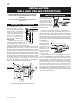
1. Cut or frame a hole in an exterior wall with a minimum
round or square opening of 12
1
/
2
" W x 12
1
/
2
" H. Secure the
firestop spacer over the opening to the interior wall.
Secure the terminal to the terminal extension plate (see fig-
ure 19).
2. Stretch the 5" diameter aluminum flexible liner to the
required length taking into account the additional length
needed for the finished wall surface. Slip the liner a mini-
mum of 2" over the inner sleeve of the air terminal and se-
cure with 3 #8 screws. Apply a heavy bead of the high tem-
perature sealant (W573-0007 not provided).
3. Using the 8" diameter flexible aluminum liner, slide over
the outer combustion air sleeve of the air terminal and se-
cure with 3 #8 screws. Seal as before.
FIGURE 18
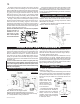
Use only approved aluminum flexible liner kits
marked:
"Wolf Steel Approved Venting" as
identified by the stamp only on the
8” outer liner.
USING FLEXIBLE VENT COMPONENTS
HORIZONTAL AIR TERMINAL INSTALLATION
VERTICAL AIR TERMINAL INSTALLATION
FIGURE 17
FIGURE 20
For safe and proper operation of the fireplace, follow
the venting instructions exactly.
All inner exhaust and outer intake vent pipe joists may
be sealed using either Red RTV high temp silicone seal-
ant or Black high temp Mill Pac with the exception of the
fireplace exhaust flue collar which must be sealed using
Mill Pac (not supplied).