
User's Manual

15
W415-0447 / B / 05.24.05
Proceed once the vent installation is complete.
Note : All gas connections must be contained within
the fireplace when complete.
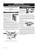
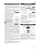
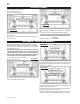
1. The fireplace is de-
signed to accept a ½"
gas supply line. The
fireplace is equipped
with a ½" manual
shut-off valve, and an 18" listed flexible gas connector.
2. The access to the gas in-
let is located on the right side
of the outer shell.
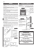
3. To ease the connection,
the shut off can be flexed out
through the side of the fire-
place where the connection
can be made.
4. When flexing any gas line, support the gas valve so that
the lines are not bent. (see Access Pg. 20).
5. Check for gas leaks by brushing on a soap and water
solution. Do not use open flame.
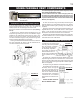
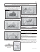
1. Move the fireplace into position.
2. Fasten the roof support to the roof using the screws
provided. The roof support is optional. In this case the vent-
ing is to be adequately supported using either an alternate
method suitable to the authority having jurisdiction or the op-
tional roof support.
3. Apply high temperature sealant (W573-0007 not pro-
vided) to the outer edge of the inner sleeve of the air terminal.
Slip a 5" diameter coupler a minimum of 2" over the sleeve
and secure using 3 screws.
4. Apply high temperature sealant
to the outer edge of the of the out-
side sleeve of the air terminal. Slip a
8" diameter coupler over the sleeve
and secure as before. Trim the 8"
coupler even with the 5" coupler end.
5. Thread the air terminal pipe
assembly down through the roof
support and attach, ensuring that
a minimum 16" of air terminal will
penetrate the roof when fastened.
If the attic space is tight, we rec-
ommend threading the Wolf Steel
vent pipe collar or equivalent
loosely onto the air terminal as-
sembly as it is passed through
the attic. The air terminal must be
located vertically and plumb.
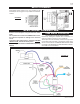
6. Remove nails from the shingles, above and to the sides
of the chimney. Place the flashing over the air terminal and
slide it underneath the sides and upper edge of the shingles.
Ensure that the air terminal is properly centred within the
flashing, giving a 3/4" margin all around. Fasten to the roof.
Do NOT nail through the lower portion of the flashing. Make
weather-tight by sealing with caulking. Where possible, cover
the sides and top edges of the flashing with roofing material.
7. Apply a heavy bead of waterproof caulking 2 inches
above the flashing. Slide the storm collar around the air ter-
minal and down to the caulking. Tighten to ensure that a
weather-tight seal between the air terminal and the collar is
achieved. Attach the other storm collar centred between the
air intake and air exhaust slots onto the air terminal. Tighten
securely. Attach the rain cap.
8. Continue adding rigid venting sections, sealing and
securing as above. Attach a 5" collapsed telescopic pipe to
the last section of rigid piping. Secure with screws and seal.
Repeat using a 8" telescopic pipe.
9. Run a bead of high temperature sealant around the
outside of the 5" collar on the fireplace. Pull the adjustable
pipe a minimum of 2" onto the collar. Secure with 3 screws.
Repeat with the 8" telescopic pipe.
10. In the attic, slide the vent pipe collar down to cover up
the open end of the shield and tighten. This will prevent any
materials, such as insulation, from filling up the 1" air space
around the pipe.
FIGURE 26
FIGURE 25
VERTICAL VENTING INSTALLATION GAS INSTALLATION
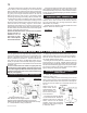
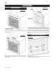
Vertical terminations may display a very active flame. If this
appearance is not desirable, the vent exit must be restricted
using restrictor plate, W500-0205. This reduces the velocity
of the exhaust gases, slowing down the flame pattern and
creating a more traditional appearance.
The plate has a series of holes to allow for adjustment.
Remove the two screws on either side of the exhaust collar
inside the firebox. Install the plate in the desired set of holes,
then replace the screws.
RESTRICTING VERTICAL VENTS
RESTRICTOR PLATE
TOP OF THE
FIREBOX
FLUE COLLAR
FIGURE 27
FIGURE 28
FIGURE 29