W415-0536 / C / 09.06.06 W415-0536 / C / 09.06.
WARNINGS & SAFETY PRECAUTIONS Do not store gasoline or other flammable vapours and liquids in the vicinity of this or any other appliance. 1. 2. 3. Installation and service must be performed by a qualified installer, service agency or the gas supplier. Follow the installation directions. 4. 5. 6. WHAT TO DO IF YOU SMELL GAS Do not try to light any appliance. Do not use any phone in your building. Immediately call your gas supplier from a neighbor's phone. Follow the gas supplier's instructions.
TABLE of CONTENTS PG2-6 introduction 6-10 18 Warnings and Safety Precautions Warranty Dimensions General Instructions General Information Care of Glass & Plated Parts Night Light Replacement venting Vent lengths Venting Specifications Air Terminal Locations 11-16 16 Door Removal Log Shipping Bracket Log Placement Glowing Embers 20 AFK / WI FACE KIT INSTALLATION REMOTE AND VALVE ACCESS 22-27 OPERATION / MAINTENANCE 27 ELECTRICAL C
napoleon products are manufactured under the strict Standard of the world recognized ISO 9001 : 2000 Quality Assurance Certificate. napoleon products are designed with superior components and materials, assembled by trained craftsmen who take great pride in their work. The burner and valve assembly are leak and test-fired at a quality test station.
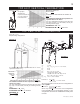
figure 1 58" 46" 37 5/8" 17 3/4" 4" DIA. 7" DIA. 5" 2" 24" 28" /" 78 8 7/8" General instructions This gas fireplace should be installed and serviced by a qualified installer to conform with local codes. Installation practices vary from region to region and it is important to know the specifics that apply to your area, for example: in Massachusetts State: • The fireplace damper must be removed or welded in the open position prior to installation of a fireplace insert or gas log.
Care of glass, and plated parts Expansion / contraction nosies during heating up and cooling down cycles are normal and are to be expected. Change in flame appearance from “HI” to “LO” is more evident in natural gas than in propane. Do not use abrasive cleaners to clean plated parts. Buff lightly with a clean dry cloth. The glass is 3/16” ceramic glass available from your Napoleon / Wolf Steel Ltd. dealer. do not substitute materials.
ELBOW VENT LENGTH VALUES DEFINITIONS for the following symbols used in the venting calculations and examples are: > - greater than > - equal to or greater than < - less than < - equal to or less than Ht - total of both horizontal vent lengths (Hr) and offsets (Ho) in feet Hr - combined horizontal vent lengths in feet Ho - offset factor: .03(total degrees of offset - 90°*) in feet Vt - combined vertical vent lengths in feet feet inches 1° 0.03 0.5 15° 0.45 6.0 30° 0.9 11.0 45° 1.35 16.
TOP EXIT / horizontal termination V1 = H1 = H2 = HR = HO = HT = HT + VT= when (Ht) > (Vt) Simple venting configuration (only one 90° elbow) figure 6 See graph to determine the required vertical rise Vt for the required horizontal run Ht. VT = 6 ft 3 ft 5 ft H1 + H2 = 3 + 5 = 8 ft .03(two 90° elbows - 90°) = .03(180° - 90°) = 2.7 ft HR + HO = 8 + 2.7 = 10.7 ft 10.7 + 6 =16.7 Formula 1: HT < 4.2 VT 4.2 VT = 4.2 x 6 = 25.2 ft 10.7 < 25.2 Formula 2: HT + VT < 24.75 feet 16.7 < 24.
TOP EXIT VERTICAL termination required vertical rise in feet when (Ht) < (Vt) See graph to determine the required vertical rise VT for the required horizontal run HT. VT horizontal vent run PLUS OFFSET in feet HT The shaded area within the lines represents acceptable values for HT and VT .
figure 12 W415-0536 / C / 09.06.
INSTALLATION WALL AND CEILING PROTECTION For optimum performance it is recommended that all horizontal runs have a minimum ¼ inch rise per foot using flexible venting. For safe and proper operation of the fireplace, follow the venting instructions exactly. Horizontal Termination: A clearance to combustibles of 2" must be maintained during the first 24” of venting when pentrating combustible walls. The firestop spacer (W500-0292) supplied with the unit should be used to maintain this clearance.
USING FLEXIBLE VENT COMPONENTS Use only approved aluminum flexible liner kits marked: “Wolf Steel Approved Venting” as identified by the stamp only on the 7” outer liner. For safe and proper operation of the fireplace, follow the venting instructions exactly.
FIREPLACE VENT CONNECTION 1. Install the 4” diameter aluminium flexible liner to the fireplace. Secure with 3 screws and flat washers. Seal the joint and screw holes using the high temperature sealant (W573-0007 not provided). 2. Install the 7” diameter aluminium flexible liner to the fireplace. Attach and seal the joints. figure 20 USING RIGID VENT COMPONENTS The vent system must be supported approximately every 3 feet for both vertical and horizontal runs.
VERTICAL VENTING INSTALLATION GAS INSTALLATION 1. Move the fireplace into position. 2. Fasten the roof support to the roof using the screws provided. The roof support is optional. In this case the venting is to be adequately supported using either an alternate method suitable to the authority having jurisdiction or the optional roof support. 3. Apply high temperature sealant to the outer edge of the inner sleeve of the air terminal.
CLEARANCE TO COMBUSTIBLES FRAMING It is best to frame your fireplace after it is positioned and the vent system is installed. Use 2x4’s and frame to local building codes. Note: In order to avoid the possibility of exposed insulation or vapour barrier coming in contact with the fireplace body, it is recommended that the walls of the fireplace enclosure be “finished” (ie: drywall/sheetrock), as you would finish any other outside wall of a home.
MANTLE CLEARANCES Combustible mantle clearance can vary according to the mantle depth. Use the graph to help evaluate the clearance needed. FIRESTOP SPACER 2" STUD 1" GAP FROM INSULATION SLEEVE 2" GAP FROM VENTING 6" figure 32 MH AE N I TG LH ET 13 12 11 10 9 8 7 0 INSULATION SLEEVE 5" TOP OF UNIT TOP OF FIREPLACE OPENING 4" 3" 11" 12" 2" 2" STAND OFF SPACER 9" 10" 8" 1 2 3 4 5 6 7 MANTLE WIDTH ELECTRICAL CONNECTION Do NOT use the fireplace if any part has been under water.
FINISHING Log SHIPPING BRACKET door REMOVAL Before the glass door can be removed, the optional front must be removed. The glass door is secured to the top front edge of the firebox. Pull the handles of the latches forward, then lift the hooks out from the slots in the door frame to release the top of the door. Next, pivot forward until the top edge of the door clears the front of the fireplace. Next gripping the sides of the door lift the door out from the retainer along the bottom of the door.
BLOWER REPLACEMENT The Napoleon PARK AVENUE comes equipped with a heat circulating blower. The blower is pre-wired and is controlled by the remote control supplied with the unit. For control details, see operation. Pg. 22. Drywall dust will penetrate into the blower bearings, causing irreparable damage. Care must be taken to prevent drywall dust from coming into contact with the blower or its compartment. Any damage resulting from this condition is not covered by the warranty policy. 1.
DECORATIVE BRICK PANEL INSTALLATION 1. Carefully remove the glass door and all logs. (Refer to the installation manual) 2. Remove the two screws holding the front portion of the rear air deflector. Remove the pilot shield by removing the two screws as illustrated. (Fig. 42) 5. Rest the bottom edge of the rear panel on top of the rear portion of the air deflector at the back of the firebox and push into place. The rear panel is held in place when both side panels are in position. 6.
afk / wi face kit installation 1. Attach screw and spacer as illustrated in Fig. 46 to the bottom of both sides of the front housing. SCREW & SPACER figure 46 2. Attach the face plate bracket provided to the top edge of the front housing using 2 #8 - 1/2” truss head screws as illustrated in Fig. 47. figure 47 figure 48 3. Lift and hook the faceplate over the spacers.
REMOTE, Receiver AND VALVE ACCESS Burner assembly removal 1a. Rectangular Front Removal Pull on the top of the optional front away from the fireplace until the male portion of the latch disengages. Tilt forward slightly and lift from the 2 shoulder screws near the bottom. 1b. Heritage and Wrought Iron Front Removal Remove the two screws in the slots located behind the inner arch. (Fig. 50) Tilt forward slightly and lift from the 2 shoulder screws near the bottom front.
OPERATION / MAINTENANCE TIME OUT If the appliance is turned on and the Receiver does not receive any command for 3 hours, it automatically turns the appliance and the Remote Control off. desired flame height. Six flame levels are included, from 1 (minimum) to 6 (maximum). An acoustic signal from the Receiver confirms the reception of the command. FIREPLACE OPERATION To operate this firplace using the remote, the pilot must be running and the gas valve turned to the “ON” position.
5. FAN SPEED SETTING This function controls the speed of the hot air circulating fan. To change the fan speed, use the UP and Down button until the cursor (small triangle) is left of the fan icon. Set to one of 4 levels included or turned off (level 4 means full speed) CHILD SAFETY LOCK-OUT This function is to deactivate control button. The function is active when the lock icon is lit.
ADDRESS SETTING PROCEDURE Use the UP and DOWN key on the transmitter until the cursor (small triangle) is left of the clock icon. From time 0:00 press the LEFT key ten times. The display will show then the transmitter address. Press the LEFT key to exit this function. The transmitter address is required to be equal to the Receiver. (Figure 62) Select, through setting of the dip switches, the address of the receiver. (Figure 64) Switch #8 must always be in the ON position (down).
dip switch number (0 = on / 1 = off) 25 figure 64 W415-0536 / C / 09.06.
OPERATING INSTRUCTIONS When lit for the first time, the fireplace will emit a slight odour for a few hours. This is a normal temporary condition caused by the curing of paints and lubricants used in the manufacturing process and will not occur again. Simply open a window to sufficiently ventilate the room. After extended periods of non-operation such as following a vacation or a warm weather season, the fireplace may emit a slight odour for a few hours.
maintenance TURN OFF THE GAS AND ELECTRICAL POWER BEFORE SERVICING THE FIREPLACE. CAUTION: Label all wires prior to disconnection when servicing controls. Wiring errors can cause improper and dangerous operation. Verify proper operation after servicing. This fireplace and its venting system should be inspected before use and at least annually by a qualified service person. The fireplace area must be kept clear and free of combustible materials, gasoline or other flammable vapours and liquids.
REPLACEMENTS Contact your dealer for questions concerning prices and availability of replacement parts. Normally all parts can be ordered through your Napoleon dealer or distributor. When ordering replacement parts always give the following information: for warranty replacement parts, a photocopy of the original invoice will be required to honour the claim. REPLACEMENT PARTS # PART No.
12 35 13 44 11 15 14 36 55 19 53 56 68 63 43 26 25 27 62 49 24 67 66 50 52 51 7 18 22 32 1 00 0:00 AUX ON 23 3 FEATURE SELECT 4 ON/OFF 2 9 21 20 5 6 W415-0536 / C / 09.06.
TROUBLE SHOOTING GUIDE Before attempting to troubleshoot, purge your unit and initially light the pilot and the main burner with the glass door open. SYMPTOM PROBLEM Main burner flame Blockage in vent. is a blue, lazy, transparent flame. Incorrect installation. TEST SOLUTION - remove blockage. In really cold conditions, ice buildup may occur on the terminal and should be removed as required. - refer to Figure 13 to ensure correct location of storm collars.
SYMPTOM PROBLEM Pilot burning; no Themostat or switch is degas to main burner; fective. gas knob is on ‘HI’; Wall switch wiring is defecwall switch / ther- tive. mostat is on. TEST SOLUTION - connect a jumper wire across the wall switch terminals; if main burner lights, replace switch / thermostat. - disconnect switch wires &connect a jumper wire across terminals 1 & 3; if the main burner lights, check the wires for defects and / or replace wires.
DATE DEALER NAME SERVICE TECHNICIAN NAME SERVICE PERFORMANCE This fireplace must be serviced annually depending on usage Fireplace Service History SPECIAL CONCERNS 32 W415-0536 / C / 09.06.
NOTES W415-0536 / C / 09.06.
NOTES W415-0536 / C / 09.06.