
User Guide

12
W415-0536 / C / 09.06.06
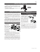
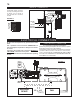
1. Fasten the roof support to the
roof using the screws provided.
The roof support is optional. In
this case the venting is to be ad-
equately supported using either an
alternate method suitable to the
authority having jurisdiction or the
optional roof support. (Fig.a)
2. Stretch the inner aluminum
Slip the liner a minimum of 2” over the inner sleeve of the
air terminal connector and secure
with 3 #8 screws. Seal using a
heavy bead of the high temperature
sealant. (Fig.b)
3. Repeat using the outer aluminum
4. Thread the air terminal connector
/ liner assembly down through
the roof. The air terminal must
be located vertically and plumb.
Attach the air terminal connector to
the roof support, ensuring that the
top of the air terminal is 16” above
the highest point that it penetrates
the roof. (Fig.c) If the attic space is
the Wolf Steel vent pipe collar or
onto the air
wall and make weather tight by
5. Apply a heavy bead of the
high temperature sealant, (W573-
0007 not provided), to the inside of
the 4” liner approximately 1” from
the end. Slip the liner a minimum
and secure with 3 #8 screws.
6.
aluminium liner,
apply sealant,
slide a mini-
mum of 2” over
the fireplace
combustion air
collar and se-
cure with 3 #8
screws.
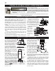
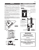
1. Cut or frame a hole in an exterior wall with a minimum
round or square opening of 11
1
/
2
” W x 11
1
/
2
” H. Secure the
Secure the terminal to the terminal extension plate if required
The cover plate of the GD-222R terminal is
13”x13” and will cover the 11 1/2” x 11 1/2” opening but if the
opening is made any larger - the terminal extension plate is
required.
2.
required length taking into account the additional length
of 2” over the inner sleeve of the air terminal and secure with
3 #8 screws. Apply a heavy bead of the high temperature
sealant.
3.
the outer combustion air sleeve of the air terminal and secure
with 3 #8 screws. Seal as before.
4.
required clearance to combustibles. Secure to the exterior
4
7
7
FIGURE 18
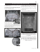
USING FLEXIBLE vENT COMPONENTS
HORIzONTAL AIR TERMINAL INSTALLATION
vERTICAL AIR TERMINAL INSTALLATION
FIGURE 19a,b&c
ROOF SUPPORT
a
DO NOT CLAMP THE
FLEXIBLE
AIR
TERMINAL
CONNECTOR
INNER FLEX
LINER
OUTER FLEX
LINER
INNER
SLEEVE
HIGH
TEMPERATURE
SEALANT
b
STORM COLLAR
FLASHING
CAULKING
WEATHER
SEALANT
2”
AIR INLET
BASE
c
CAULKING
SCREWS
#10x2"
PIPE
7" FLEX
2" OVERLAP
4"FLEX
PIPE
SEALANT
SEALANT
HI-TEMP
TERMINAL
EXTENSION
PLATE
CAULKING
FIGURE 17
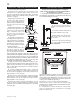
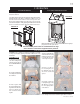
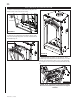
5. Remove nails from the
shingles, above and to the
sides of the chimney. Place
terminal connector leaving a
min. 3/4” of the air terminal
connector showing above
sides and upper edge of
the shingles. Ensure that
the air terminal connector
is properly centred within
margin all around. Fasten to
the roof. Do not nail through
the lower portion of the
6. Aligning the seams of the terminal and air terminal
connector, place the terminal over the air terminal connector
making sure the liner goes into the hole in the terminal.
Secure with the three screws provided. (Fig.c)
7. Apply a heavy bead of weatherproof caulking 2 inches
between the air inlet base and the storm collar. Install the
storm collar around the air terminal connector and slide
down to the caulking. Tighten to ensure that a weather-tight
seal between the air terminal connector and the collar is
achieved. (Fig.c)