
User Guide

14
W415-0536 / C / 09.06.06
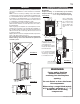
FLUE COLLAR
RESTRICTOR PLATE
TOP OF THE
FIREBOX
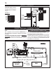
1.
2. The access to the gas inlet is
located on the right side of the outer
shell.
3.
must all be within the outer shell.
4.-
port the gas valve so that the lines
are not bent.
5. Check for gas leaks by brushing
on a soap and water solution. Do not
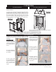
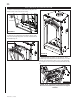
1.
2. Fasten the roof support to the roof using the screws
provided. The roof support is optional. In this case the vent-
ing is to be adequately supported using either an alternate
method suitable to the authority having jurisdiction or the
optional roof support.
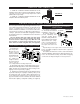
3. Apply high temperature seal-
ant to the outer edge of the inner
sleeve of the air terminal. Slip a 4”
diameter coupler a minimum of 2”
over the sleeve and secure using
3 screws.
4 Apply high temperature seal-
ant to the outer edge of the of the
outside sleeve of the air terminal.
Slip a 7” diameter coupler over
the sleeve and secure as before.
Trim the 7” coupler even with the
4” coupler end.
5 Thread the air terminal pipe
assembly down through the roof
support and attach, ensuring that
a minimum 16” of air terminal will
penetrate the roof when fastened.
The air terminal must be located
vertically and plumb.
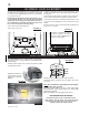
6. Remove nails from the shin-
gles, above and to the sides of
over the air terminal and slide it
underneath the sides and upper edge of the shingles. Ensure
-
ing a 3/4” margin all around. Fasten to the roof. Do NOT nail
by sealing with caulking. Where possible, cover the sides and
7. Apply a heavy bead of waterproof caulking 2 inches
-
minal connector and down to the caulking. Tighten to ensure
that a weather-tight seal between the air terminal and the
collar is achieved.
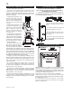
Continue adding rigid venting sections, sealing and
securing as above. Attach a 4” collapsed telescopic pipe to
the last section of rigid piping. Secure with screws and seal.
Repeat using a 7” telescopic pipe.
Run a bead of high temperature sealant around the
pipe a minimum of 2” onto the collar. Secure with 3 screws.
Repeat with the 7” telescopic pipe.
10. In the attic, slide the vent pipe collar down to cover up
the open end of the shield and tighten. This will prevent any
around the pipe.
VENT PIPE
SHIELD
VENT
PIPE
COLLAR
FIGURE 24
FIGURE 23
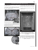
vERTICAL vENTING INSTALLATION GAS INSTALLATION
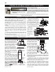
appearance is not desirable, the vent exit must be restricted
using restrictor plate, W500-0205. This reduces the velocity
creating a more traditional appearance.
The plate has a series of holes to allow for adjustment.
Remove the two screws on either side of the exhaust collar
then replace the screws.
It is recommend to secure in the third set of holes which
causes the greatest amount of restriction for vent length
between 15 and 30 feet.
RESTRICTING vERTICAL vENTS
FIGURE 25
FIGURE 26
FIGURE 27
22
1
/
8
"
21"
4" DIA.
7" DIA.
17
3
/
4
"
13
7
/
8
"
28"
14"
7
/
8
"
46"
58"
2"
8
7
/
8
"
28"
33
5
/
8
"
STORM COLLAR
FLASHING
CAULKING
WEATHER
SEALANT
2”
AIR INLET
BASE