
Blowtorch User Manual


5
W415-0689 / 06.25.08
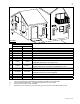
FIGURES 1a-c
DIMENSIONS
Note: All gas connections must be contained within the
appliance when complete.
1. The appliance is designed to accept a 1/2” gas supply line. The
appliance is equipped with a 1/2” manual shut-off valve.
2. The access to the gas inlet is located in the bottom of the
cabinet.
3. The shut off valve / fl ex connector assembly must always be
contained within the cabinet.
4. When fl exing any gas line, support the gas valve so that the
lines are not kinked.
5. Check for gas leaks by brushing on a soap and water
solution.
GAS INSTALLATION
11
/
16
49
GAS LINE
ACCESS
ELECTRICAL
ACCESS
3
/
8
36
1
/
2
1
9
/
16
7
15
13
W385-0380
SHUT OFF
VALVE
FLEX
CONNECTOR
INSTALLATION