
Installation Instruction
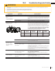

Table Of Contents

W415-1768 / B / 08.10.18
EN
62
troubleshooting
!
WARNING
• Always light the pilot whether for the fi rst time or if the gas supply has run out, with the glass door open or
removed.
• Turn off gas and electrical power before servicing the appliance.
• Appliance may be hot. Do not service until appliance has cooled.
• Do not use abrasive cleaners
27.1
symptom problem test solution
Main burner fl ame is a
blue, lazy, transparent
fl ame.
(This is not applicable
in outdoor appliances)
Blockage in vent. - Remove blockage. In really cold conditions, ice buildup may occur
on the terminal and should be removed as required. (To minimize this
from reoccuring, the vent lengths that pass through unheated spaces
(attics, garages, crawl spaces) be wrapped with an insulated mylar
sleeve).
Incorrect installation. - Refer to “venting” section to ensure correct installation.
Flames are consistently
too large or too small.
Carboning occurs.
Appliance is over-fi red or under-
fi red.
- Check pressure readings:
Inlet pressure can be checked by turning screw (A) counter-clock-
wise 2 or 3 turns and then placing pressure gauge tubing over the
test point. Gauge should read as described on the chart below.
Check that main burner is operating on ‘HI’. Outlet pressure can be
checked the same as above using screw (B). Gauge should read as
described on the chart below. Check that main burner is operating
on ‘HI’. After taking pressure readings, be sure to turn screws
clockwise fi rmly to reseal. DO NOT OVER TORQUE.
Leak test with a soap and water solution.
Air shutter improperly adjusted.
- Return air shutter to specifi ed opening, see “venturi adjustments”
section in the installation manual.
Carbon is being
deposited on glass,
logs, rocks, media, or
combustion chamber
surfaces.
Air shutter is blocked. - Ensure air shutter opening is free of lint or other obstructions.
Flame is impinging on the glass,
logs, rocks, media or combus-
tion chamber.
- Ensure the media is positioned correctly in the appliance.
- Open air shutter to increase the primary air.
- Check the input rate: check the manifold pressure and orifi ce size as
specifi ed by the rating plate.
- Ensure door gaskets are not broken or missing and the seal is tight.
- Ensure vent liners are free of holes and well sealed at all joints.
- Check that minimum rise per foot (meters) has been adhered to for
any horizontal venting.
White / grey fi lm forms. Sulphur from fuel is being depos-
ited on glass, logs, or combus-
tion chamber surfaces.
- Clean the glass with a recommended gas fi replace glass cleaner. DO
NOT CLEAN GLASS WHEN HOT.
- If deposits are not cleaned off regularly, the glass may become
permanently marked.
Exhaust fumes smelled
in room, headaches.
Appliance is spilling.
(This is not applicable in outdoor
appliances).
- Check door seal.
- Check for exhaust damage.
- Check that venting is installed correctly.
- Room is in negative pressure; increase fresh air supply.
INSERT
PHOTO
OF VALVE
HERE
symptom problem test solution
Pilot will not light. Makes
noise with no spark at
pilot burner.
Wiring: short, loose, or damaged
connections
(poor fl ame rectifi cation).
- Verify the thermocouple/sensor is clean and the wiring is undamaged.
- Verify the interrupter block is not damaged or too tight. Verify
connections from pilot assembly are tight; also verify the connections
are not grounding out to any metal. (Remember, the fl ame carries the
rectifi cation current, not the gas. If fl ame lifts from pilot hood, the circuit
is broken. A wrong orifi ce or too high of an inlet pressure can cause the
pilot fl ame to lift)*. The sensor rod may need cleaning.
No signal from remote with no
pilot ignition.
- Reprogram receiver code.
- Replace receiver.
Poor grounding. - Verify the valve and pilot assembly is properly grounded
Improper switch wiring.
- Troubleshoot the system with the simplest on/off switch.
Dirty, painted, or damaged pilot
and/or dirty sensor rod.
- Clean sensor rod with a green Scotch-Brite™ pad to remove any
contamination that may have accumulated. Verify continuity with
multimeter with ohms set at the lowest range.
Pilot sparks but will
not light.
Gas supply. - Verify that the incoming gas line ball valve is “open”.
- Verify that the inlet pressure reading is within acceptable
limits, inlet pressures must not exceed 13” W.C. (32,4mb).
Out of propane gas. - Fill the tank.
Pilot supply line may contain
air.
- Repeat ignition process several times or purge the pilot
supply line.
Incorrect wiring / grounding. - Ensure correct polarity of wiring of thermocouple (if
equipped).
- Verify pilot assembly/valve are properly grounded.
Receiver (if equipped). - Reset program: hold reset button on receiver and wait for 2
beeps. Release after second beep. Press small fl ame button
on remote within 20 seconds, you will hear an additional
beep (this signals a successful reset).
- Replace receiver.
Valve. - Check valve and replace if necessary (Do not to overtighten
thermocouple).
Burner continues to
spark and pilot lights
but main burner
does not light.
Short or loose connection in
sensor rod.
- Verify all connections. Verify the connections from the pilot
assembly are tight. Also, verify these connections are not
grounding out to any metal.
Dirty, painted, or damaged
pilot assembly components.
- Clean using a green Scotch-Brite™ pad to remove any
contamination that may have accumulated on the sensor
rod, pilot hood, ignitor, or fl ame sensor. Verify continuity with
multimeter with ohms set at the lowest range.
Remote wall switch
is in “off” position;
burner comes on.
Wall switch mounted upside
down.
- Reverse.
Remote wall switch and/or
wire is grounding.
- Replace.
- Check for ground (short); repair ground or replace wire.
Faulty wire - Replace.
Remote and / or
receiver is not
functioning properly.
Remote controls lights but
no spark or fl ame. (Remote is
locked out).
- Reset by turning power source off then on.
Receiver or remote has low battery.
- Replace batteries.
Appliance functions but does not
respond to receiver / remote
- Ensure appliance is being operated by the same device that turned it
on. Remote controls functions if appliance was turned on by remote.
Receive controls functions if appliance was turned on by receiver.
Error with synchronizing. - Reset receiver and remote.
Remote too far away from receiver.
- Refer to “wiring diagram” section.
Wire connector pins are bent. - Straighten pins.
Valve wiring is damaged. - Replace valve.
symptom problem test solution
The following applies specifi cally to the SIT system only:
Pilot will not light.
Makes no noise with
no spark at pilot
burner. (Lights and
blower operate, if
equipped).
Ignition box has been locked
out.
Choose one of the 4 methods below to reset the system.
1. To reset ignition box when locked out. Turn off power supply
and remove batteries (if used) from the back up battery pack.
2. To reset the DFC Board when the board goes into a lock
out condition and the LED is blinking 3 times using the
transmitter on/off button:
Step 1: Turn the system off by pressing the on/off
button to turn the system off.
Step 2: After approximately 2 seconds press the on/
off button on the transmitter again. The DFC Board will
reset and the ignition sequence will start again.
3. To reset the DFC Board when the board goes into a lock out
condition and the LED is blinking 3 times by cycling fl ame:
Step 1: In the manual fl ame control mode, use the down
arrow button to reduce the fl ame to off, indicated by the
word OFF displayed on the transmitter LCD screen.
Step 2: Wait approximately 2 seconds and press the up
arrow button, the ignition sequence will start.
symptom problem test solution
The following applies specifi cally to the Maxitrol system only:
Pilot lights.
No gas fl ow.
Manual override knob is in the
“MAN” position.
- Turn the knob to the “ON” position.
Valve is not functioning properly. - Valve is on pilot fl ow. Turn to the high setting, double click the large
fl ame button on the remote.
- Replace valve. Do not overtighten.
No spark after pilot
ignition. Valve turns off
in one minute and does
not operate.
Minimal voltage from thermocou-
ple or resistance in circuit ports
(Parts include: “ON/OFF” switch,
receiver, thermocurrent connec-
tions or temperature switches).
- Measure the voltage, it should read a least 5mV. The spade
connector is on the outer surface beside the magnet nut. Verify with
manufacturer the drop time, after thermocouple is heated measure
the drop time.
No pilot ignition
(5 second continuous
beep).
Switch is in “OFF” position on
the valve.
- Switch to “ON“ position.
Wiring is loose. - Ensure wiring is properly secured.
Receiver (if equipped). - Reset program: hold reset button on receiver and wait for 2 beeps.
Release after second beep. Press small fl ame button on remote
within 20 seconds, you will hear an additional beep (this signals a
successful reset).
- Replace receiver.
Wire connector pins are bent. - Straighten pins.
Valve wiring is damaged. - Replace valve.
Burner continues to
spark and pilot lights
but main burner does
not light.
Connections are loose or dam-
aged.
- Verify the thermocouple is clean and the wiring between it and the
valve is undamaged.
- Verify the interrupter block is not damaged or too tight.
Remote and / or re-
ceiver is not function-
ing properly.
Receiver not communicating
properly.
- Hold reset button on the receiver and wait for 2 beeps. Release after
second beep. Press the small fl ame button on the remote within
20 seconds, you will hear an additional beep (this signals that the
receiver has been successfully reset).
*Maximum inlet pressure not to exceed 13” w.c.
Pressure Natural Gas
(inches)
Natural Gas
(millibars)
Propane
(inches)
Propane
(millibars)
Inlet
*7”
(minimum 4.5”)
17.4mb
(minimum 11.2mb)
13”
(minimum 11”)
32.4mb
(minimum 27.4mb)
Outlet
3.5” 8.7mb 10” 24.9mb
If back up batteries are installed, they must also be removed to
re-program
note:
Starting from off, press the on button on the transmitter. Approximately 4 seconds on/off button is pressed, the ignition
board will start the spark. The fi rst try for ignition will last approximately 60 seconds. If there is no fl ame ignition (rectifi cation),
the board will stop sparking for approximately 35 seconds. After the wait time, the board will start the second try for ignition
by sparking for approximately 60 seconds. If there is still no positive ignition, the board will go into lock out.
note:
symptom problem test solution
Motor is turning,
frequent beeping
occurs.
Receiver batteries low. - Replace batteries.
Lights or blower
won’t function (if
equipped).
Control module switch in
wrong position.
- Verify ON/OFF switch is in the “I” position which denotes on.
COM switch is unplugged. - Verify “COM” switch is plugged into the front of the control
module.
Flames are very
aggressive.
Door is ajar. - Ensure door is secured properly.
Venting action is too great. - Check to ensure venting is properly sealed or restrict vent
exit with restrictor plate. (Not available in all appliances).
Appliance won’t per-
form any functions.
No power to the system.
- Check breaker to verify it’s in the “on” position.
Receiver switch in wrong
position (if equipped).
- Verify that the 3 position switch on the receiver is in the
remote position (middle).
Transmitter isn’t operational. - Check battery power and battery orientation.