
Castlemore Series Manual
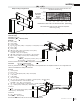
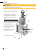
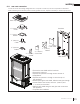
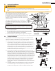
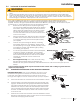
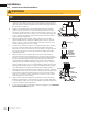
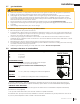
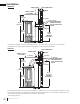
Table Of Contents

EN
W415-2360 / A / 10.31.19
29
installation
3.8 minimum clearance to combustibles
!
WARNING
• Risk of fi re, explosion, or asphyxiation. Ensure there are no ignition sources such as sparks or open fl ames.
• Support gas control when attaching gas supply pipe to prevent damaging gas line.
• Always light the pilot whether for the fi rst time or if the gas supply has run out with the glass door opened
or removed. Purging of the gas supply line should be performed by a qualifi ed service technician. Ensure
that a continuous gas fl ow is at the burner before closing the door. Ensure adequate ventilation. For gas and
electrical locations, see “dimensions” section.
• All gas connections must be contained within the appliance when complete (gas fi replaces only).
• High pressure will damage valve. Disconnect gas supply piping before testing gas line at test pressures above
1/2 PSIG.
• Valve settings have been factory set, do not change.
Installation and servicing to be done by a qualifi ed installer.
• Move the appliance into position and secure.
• If equipped with a fl ex connector, the appliance is designed to accept a 1/2” (13mm) gas supply. Without the
connector, it is designed to accept a 3/8” (9.5mm) gas supply. The appliance is equipped with a manual shut
off valve to turn off the gas supply to the appliance.
• Connect the gas supply in accordance to local codes. In the absence of local codes, install to the current
CAN/CSA-B149.1 Installation Code in Canada or to the current National Fuel Gas Code, ANSI Z223.1 / NFPA
54 in the United States.
• When fl exing any gas line, support the gas valve so that the lines are not bent or kinked.
• The gas line fl ex-connector should be installed to provide suffi cient movement for shifting the burner assembly
on its side to aid with servicing components.
• Check for
g
as leaks b
y
brushin
g
on a soa
p
and water solution. Do not use o
p
en fl ame.
3.7 gas installation
* HORIZONTAL VENT SECTIONS:
A minimum clearance of 1" (25mm) at the bottom and sides and 2" (51mm) at the top of the vent pipe in all
horizontal runs to combustibles is required. Use fi restop spacer W010-1313 and shield W585-0267 (supplied).
* VERTICAL VENT SECTIONS:
A minimum of 1" (25mm) all around the vent pipe on all vertical runs to combustibles is required. Use fi restop
spacer W010-1313 (supplied).
** For top vent vertical termination, see "rear exit" section for specifi c clearances.
At a distance of 2" (51mm) from the wall, installation or service to the blower may not be practical. A minimum of
5" (127mm) will be required in order to install or service the blower.
Minimum clearance to combustible construction from appliance and vent surfaces:
A - 2" (51mm)
B - 5" (127mm)
C - 2" (51mm)
Combustible Framing:
- 1" (25mm) to bottom and sides of the vent pipe*
- 2" (51mm) to top of the vent pipe*
NOTE: Appliance should not be installed directly on
carpeting.
Rear Exit:
- 47 1/2" (120.7cm) to ceiling from base of the appliance
Top Exit:
- 51" (129.5cm) to ceiling from base of the appliance**
BACK WALL
SIDE WALL
BACK WALL
SIDE WALL