This gas grill must be used only outdoors in a well-ventilated space and must not be used inside a building, garage, screened-in porch, gazebo or any other enclosed area. EN APPLY SERIAL NUMBER LABEL FROM CARTON Serial No. XXXXXX000000 MODEL NO. DE PG.15 DO NOT DISCARD LE485SB, LE485RSB, LE485RSIB DANGER IF YOU SMELL GAS: • Shut off gas to the appliance. • Extinguish any open flame. • Open lid.
EN THANK YOU FOR CHOOSING NAPOLEON NAPOLEON products are designed with superior components and materials, and are assembled by trained craftsmen who take great pride in their work. The burner and valve assembly are leak tested and test-fired at a quality test station. This grill has been thoroughly inspected by a qualified technician before packaging and shipping to ensure that you, the customer, receive the quality product you expect from NAPOLEON.
WARNING! Failure to follow these instructions could result in property damage, personal injury or death. Read and follow all warnings and instructions in this manual prior to operating grill. Safe Operating Practices • • • • • • • • • • • • • • • • • • • • • • • • • • • • • • • • • • • • • • • • This gas grill must be assembled exactly according to the instructions in the manual.
EN Electrical Precautions WARNING! Failure to follow these instructions could result in property damage, personal injury or death. • • • • • • • • • • • 230V - 50HZ -.09A -20W – type 2 transformer (Electrical Rating - Internal Light Models Only). To protect against electric shock, do not immerse cord or plugs in water or other liquid. Unplug from the outlet when not in use and before cleaning. Allow to cool before putting on or taking off parts.
Gas Hose • • • • • • If the hose and regulator are not included by the manufacturer, then only hoses and regulators which meet national and regional codes are to be used. Ensure that the hose does not come into contact with grease, other hot drippings, or any hot surfaces on the appliance. Check hose regularly. In the case of rips, melting or wear, replace hose before using the appliance. The recommended hose length is 0.5m. The hose must not be longer than 1.5m.
Leak Testing Instructions WARNING! A leak test must be performed annually and each time a cylinder is hooked up or if a part of the gas system is replaced. EN Warning! Never use an open flame to check for gas leaks. Be certain no sparks or open flames are in the area while you check for leaks. Sparks or open flames will result in a fire or explosion, damage to property, serious bodily injury, or death.
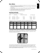
Lighting Instructions EN Side Burner Lights Left Burner Rear Burner Centre Burner Right Burner Side Burner Igniter Off Position WARNING! Open lid. WARNING! Ensure all burner controls are in the off position. Turn on the gas supply valve. Main Tube Burner Lighting Rear Burner Lighting (If equipped) Side Burner Lighting (If equipped) 1. Open grill lid. 1. Open grill lid. 1. Open side burner cover. 2. Push and turn any main burner knob slowly to the ’hi’ position.
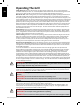
EN Operating The Grill Initial Lighting: When lit for the first time, the gas grill emits a slight odor. This is a normal temporary condition caused by the “burn-in” of internal paints and lubricants used in the manufacturing process and does not occur again. Simply run the main burners on high for approximately one-half hour. Main Burner Use: When searing foods, we recommend preheating the grill by operating all main burners in the high position with the lid closed for approximately 10 minutes.
1. Follow the infrared side burner lighting instructions and operate on high for 5 minutes with the lid opened or until the ceramic burners glow red. 2. Place food on grills and cook according to times listed in the Infrared Grilling Chart. 3. Depending upon your taste, continue cooking over infrared burners on high, medium or low, turning food frequently, or place food on the main burner area of the grill, close lid, and allow oven temperature to slowly finish cooking your food.
Infrared Grilling Chart EN Food Control Setting Cooking Time Helpful Suggestions Steak High setting 2 min. each side. 4 min. – Rare High setting 2 min. each side then medium setting. 6 min. – Medium High setting 2 min. each side then medium setting. 8 min. – Well done When selecting meat for grilling, ask for marbled fat distribution. The fat acts as a natural tenderizer while cooking and keeps it moist and juicy. High setting 2 min. each side. 4 min. – Rare High setting 2 1/2 min.
Maintenance / Cleaning Instructions 11 We recommend this gas grill be thoroughly inspected and serviced annually by a qualified service person. At all times keep the gas grill area free from combustible materials, gasoline and other flammable vapors and liquids. Do not obstruct the flow of ventilation and combustion air. Keep the cylinder enclosure ventilation openings (located on the cart sides and at the front and back of the bottom shelf) free and clear from debris.
EN life of the bulb. To clean the lens, first soak it in hot soapy water, then clean with a rag and non abrasive cleaner. To reinstall the lens, simply snap it back into the housing. WARNING! Accumulated grease is a fire hazard. Drip Pan: Clean the drip pan frequently (every 4 – 5 uses or as often as required) to avoid grease buildup. Grease and excess drippings pass through to the drip pan, located beneath the gas grill and accumulate in the disposable grease tray below the drip pan.
Troubleshooting EN Problem Possible Causes Solution Low heat / Low flame when valve turned to high. For propane - improper lighting procedure. Ensure lighting procedure is followed carefully. All gas grill valves must be in the off position when the tank valve is turned on. Turn tank on slowly to allow pressure to equalize. See lighting instructions. For natural gas - undersized supply line. Pipe must be sized according to installation code. For both gases - improper preheating.
EN KEEP YOUR RECEIPT AS PROOF OF PURCHASE TO VALIDATE YOUR WARRANTY. Ordering Replacement Parts Warranty Information MODEL: DATE OF PURCHASE: SERIAL NUMBER: (Record information here for easy reference) Before contacting the Customer Solutions Department, check the Napoleon Website for more extensive cleaning, maintenance, troubleshooting and parts replacement instructions at www.napoleongrills.com.
Dieser Gasgrill darf nur an einem gut belüfteten Ort im Freien benutzt werden, nicht jedoch in einem Gebäude, einer Garage oder einem anderen geschlossenen Bereich. SERIENNUMMER-AUFKLEBER VOM KARTON HIER ANBRINGEN Seriennr. XXXXXX000000 Model-Nr. DE BITTE SORGFÄLTIG AUFBEWAHREN LE485SB, LE485RSB, LE485RSIB GEFAHR WENN ES NACH GAS RIECHT: • Gaszufuhr zum Gerät absperren. • Flammen löschen. • Haube öffnen.
DE VIELEN DANK, DASS SIE SICH FÜR NAPOLEON ENTSCHIEDEN HABEN! NAPOLEON-Produkte werden ausschließlich mit Komponenten und Materialien von höchster Qualität hergestellt, die von unseren geschulten und qualitätsorientierten Technikern montiert werden. Die Brenner und Ventile werden vor Auslieferung auf Dichtigkeit getestet und einem Zündtest unterzogen.
ACHTUNG! Ein Nichtbefolgen dieser Anleitung kann durch Brände oder Explosionen zu Sachschäden und Körperverletzungen, auch zu tödlichen, führen. Vorsichtsmassnahmen • • • • • • • • • • • • • • • • • • • • • • • • • • • • • • • • • • • • • • • • • • • • • • • • • • Bei der Montage dieses Gasgrills müssen die Anweisungen im Handbuch genau befolgt werden.
Elektrische Schutzmaßnahmen WARNUNG! Nichtbefolgung dieser Anweisungen kann zu Sachschäden, Körperverletzung oder Tod führen. • • DE • • • • • • • • • 230V - 50HZ -.09A -20W type 2 transformator (Leistungschild nur für Modelle mit interner Beleuchtung). Um sich vor Stromschlag zu schützen, tauchen Sie das Kabel oder die Stecker nicht in Wasser oder andere Flüssigkeiten. Ziehen Sie den Netzstecker heraus, wenn das Gerät nicht benutzt wird und bevor Sie den Grill reinigen.
ACHTUNG! • • Schlauch nicht unterhalb der Auffangschale verlegen. Schlauch nicht im Zwischenraum zwischen dem unteren Regal und der hinteren Abdeckung verlegen. Schlauch nicht über die Oberseite der hinteren Abdeckung verlegen. Alle Schlauchanschlüsse mit zwei Rohrschlüsseln fest anziehen. Kein Teflon-Abdichtungsband oder Dichtungskitt für die Rohrverbindungen verwenden. Den Schlauch von heißen Oberflächen fernhalten. Schmelzen des Schlauchs kann zu Bränden führen.
Diese Einheit ist mit einem internen Druckregler ausgestattet, der den Gasdruck stabilisiert und die Grillleistung verbessert. Dieser Druckregler ist nicht anpassbar. An der Seite des Druckreglers befindet sich ein Druckhahn. Dieser kann von einem entsprechend ausgebildeten Kundendiensttechniker dazu verwendet werden, die Funktion des Druckreglers zu überprüfen.
Zündanleitung Seiten Brenner Lampen Linker Brenner Hinterer Brenner Mittlerer Brenner Rechter Brenner Zünder Des Seiten Brenners Ausschaltstellung ACHTUNG! Haube öffnen. ACHTUNG! Stellen Sie sicher, dass alle Brenner-Bedienelemente auf „OFF” (Aus) gestellt sind, und öffnen Sie das Gasventil an der Gasquelle. Anzünden des Hauptbrenners Anzünden des rückseitigen Brenners (Rotisseriebrenner) (Falls vorhanden) Anzünden der Seitenbrenner (Falls vorhanden) 1. Haube öffnen 1. Haube öffnen. 1.
DE Betrieb Des Grillgeräts Beim allerersten Erhitzen gibt der Gasgrill einen leichten Geruch ab. Der Geruch wird durch das „Einbrennen” der Innenlacke und Verdunsten der Schmiermittel aus der Fertigung verursacht, ist ganz normal und tritt später nicht mehr auf. Vor der ersten Benutzung sollten Sie darum die Hauptbrenner etwa eine halbe Stunde mit größter Hitze brennen lassen.
Verwendung der Seitenbrennerflamme: Der Seitenbrenner kann wie ein normales Gaskochfeld verwendet werden und eignet sich zur Zubereitung von Soßen, Suppen usw. Der Gasgrill sollte so positioniert werden, dass der Seitenbrenner möglichst windgeschützt ist, da starke Winde die Leistung des Seitenbrenners beeinträchtigen können. Seitenbrenner NICHT zum Frittieren verwenden, da das Kochen mit Öl zu gefährlichen Bedingungen führen kann. Der empfohlene Durchmesser für Pfannen und Töpfe ist 20 bis 25 cm.
DE Infrarotwärme Die meisten Menschen wissen nicht, dass unsere natürliche Wärmequelle, die Sonne, die Erde hauptsächlich mit Infrarotenergie wärmt. Infrarotenergie ist eine Form der elektromagnetischen Energie mit einer etwas größeren Wellenlänge als die Farbe Rot des Lichtspektrums, aber einer etwas geringeren als die der Radiowellen. Diese Energie wurde 1800 von Sir William Herschel entdeckt, der das Sonnenlicht mit Hilfe eines Prismas in seine Bestandteile zerlegte.
Infrarot-Grilltabelle Grillgut Brennerstufe Grillzeit Empfehlungen Steak, 2,5 cm dick 2 Min. pro Seite auf höchster Stufe Englisch: 4 Min. 2 Min. pro Seite auf höchster Stufe, dann mittlere Stufe Medium: 6 Min. Durchwachsenes Fleisch eignet sich am besten zum Grillen. Das Fett macht das Fleisch zart und saftig. 2 Min. pro Seite auf höchster Stufe, dann mittlere Stufe Durch: 8 Min. 2 Min. pro Seite auf höchster Stufe Englisch: 4 Min. 2,5 Min. pro Seite auf höchster Stufe Medium: 5 Min.
Wartung, Pflege Und Reinigung Der Gasgrill sollte jährlich von einem zugelassenen Wartungsdienst überprüft und gewartet werden. Brennbare Materialien, Benzin und andere brennbare Dämpfe und Flüssigkeiten müssen entfernt vom Gasgrill gelagert werden. Luftwege zur Belüftung und zum Brenner nicht blockieren. Lüftungslöcher des Gasflaschenschranks (an den Grillwagenseiten und der Vorder- und Rückseite des unteren Regalbodens) stets frei von Schmutz und Ablagerungen halten.
auf der Bedienleiste zum Abrieb der aufgedruckten Beschriftung führen. Das Innere Des Gasgrills: Grillroste entfernen. Gusseiserne Seiten und die Innenseite der Haube mit einer weichen Messingdrahtbürste von losem Schmutz befreien. Anbratplatten mit einem Spachtel oder Schaber abkratzen, und die Asche mit einer Drahtbürste beseitigen. Anbratplatten abnehmen, und die Brenner mit einer Messingdrahtbürste reinigen. Den Schmutz aus dem Inneren des Gasgrills in die Tropfpfanne fegen.
ACHTUNG! Bei der erneuten Installation des gereinigten Brenners unbedingt sicherstellen, dass das Ventil/die Öffnung in das Brennerrohr führt, bevor der Gasgrill angezündet wird. Wenn das Ventil sich nicht innerhalb des Brennerohrs befindet, kann es zu Brand oder Explosion kommen. DE Alugussteile: regelmäßig mit warmem Seifenwasser säubern. Normalerweise rostet Aluminium nicht. Durch die hohen Temperaturen und die Umwelteinflüsse kann es jedoch zu einem Oxidieren der Oberfläche kommen.
Fehlerbehebung Problem Mögliche Ursache Lösung Bei höchster Brennerstufe zu niedrige Hitze und Flamme. Bei Propangas – die Die Anweisungen für das Anzünden genau befolgen. Anweisungen für das Anzünden Alle Gasgrillventile müssen sich in der Stellung „OFF” wurden nicht befolgt. (Aus) befinden, wenn das Ventil für die Gaszufuhr geöffnet wird. Die Gaszufuhr langsam öffnen, um Druckausgleich zu ermöglichen. Siehe Anweisungen für das Anzünden. Bei Erdgas – Leitung für die Gaszufuhr zu klein.
BEWAHREN SIE IHRE QUITTING ALS KAUFNACHWEIS AUF, UM IHREN GARANTIEANSPRUCH ZU VALIDIEREN. BESTELLUNG VON ERSATZTEILEN GARANTIE-INFORMATIONEN DE MODELL: KAUFDATUM: SERIENNUMMER: (Alle für einen Garantieanspruch benötigten Informationen hier aufzeichnen) Bevor Sie sich mit dem Kundenlösungen setzen, besuchen Sie bitte die Napoleon-Website unter www.napoleongrills.com, um ausführlichere Informationen zu Reinigung, Wartung und Pflege, Fehlerbehebung und Ersatzteile zu erhalten.
Caution! During unpacking and assembly we recommended you wear work gloves and safety glasses for your protection. Although we make every effort to make the assembly process as problem free and safe as possible, it is characteristic of fabricated steel parts that the edges and corners might be sharp and could cause cuts if handled incorrectly. Getting Started 1. Remove all cart panels, hardware, and grill head from carton. Raise lid and remove any components packed inside.
N430-0002 x1 x16 N570-0073 (1/4-20 X 3/8”) non revolving caster- left side Nicht drehbare Rollen - links www.napoleongrills.
x4 N570-0080 (#14 x 1/2”) www.napoleongrills.
x6 N570-0080 (#14 x 1/2”) N570-0078 (M4 X 8mm) LE485RSIB MODEL LE485RSIB MODELLE www.napoleongrills.
x4 N570-0080 (#14 x 1/2”) N430-0002 x1 x4 N570-0080 (#14 x 1/2”) www.napoleongrills.
x4 N570-0091 (1/4-20 X 1/2”) WARNING! Propane Only - To avoid assembly difficulties, prior to mounting the grill head, remove zip tie holding regulator. This was installed at the factory to protect the regulator hose during shipping and is no longer required. (Take care when removing the tie not to damage the hose). Ensure the regulator hose does not become pinched between the grill head and the cart.
x2 x1 N570-0073 (1/4-20 X 3/8”) N640-0001 Clip wires from lights to side panel using retainer clip supplied. Lampen-Kabel mit dem mitgelieferten Schlauchhalter-Clip am Seitenpaneel befestigen. LE485RSIB MODEL LE485RSIB MODELLEN x1 N570-0080 (#14 x 1/2”) 1 2 3 www.napoleongrills.
x4 x4 N570-0080 (#14 x 1/2”) N570-0088 (10-24 X 1/2”) x4 N735-0007 (1/4”) LE485SB/LE485RSB MODEL LE485SB/LE485RSB MODELLEN Warning! Do not over tighten the screws, as this will cause the handle to crack. ACHTUNG! Schrauben nicht zu fest anziehen, da dies zum Brechen des Griffs führen kann. x8 N570-0073 (1/4-20 X 3/8”) LE485RSIB MODEL LE485RSIB MODELLEN Warning! Do not over tighten the screws, as this will cause the handle to crack.
x4 N570-0082 (1/4-20 X 5/8”) x4 x4 N735-0001 x4 N570-0082 (1/4-20 X 5/8”) N735-0001 N160-0023 x1 LE485RSIB MODEL LE485RSIB MODELLEN Fit orifice into burner tube and secure with hose retainer clip supplied. Öffnung in die Brennerleitung einpassen und mit dem beiliegendenSchlauchhalterClip sichern. WARNING! The Infrared side burner is supplied with a drip pan which holds only a minimal amount of grease. To prevent grease fires, the pan must be cleaned after each use.
x4 x4 N570-0082 (1/4-20 X 5/8”) N735-0001 N160-0023 x1 LE485SB/LE485RSB MODEL LE485SB/LE485RSB MODELLEN Fit orifice into burner tube and secure with hose retainer clip supplied. Öffnung in die Brennerleitung einpassen und mit dem beiliegendenSchlauchhalterClip sichern. www.napoleongrills.
x4 N570-0099 (#14 x 3/4”) N340-0007 x4 N485-0016 (32mm) N485-0017 (22mm) x2 1 1/4” (32mm) TOP OBEN BOTTOM UNTEN 7/8” (22mm) www.napoleongrills.
x2 N105-0011 N160-0022 x2 2 1 3 4 www.napoleongrills.
www.napoleongrills.
www.napoleongrills.
Rotisserie Kit Assembly Instruction (optional) Assemble rotisserie kit components as shown. Anweisungen für die Montage des Drehspieß-Sets (optionale) Komponenten des Drehspieß-Sets wie gezeigt montieren. Ensure stop bushing is tightened on the inside of hood casting. Sicherstellen, dass die Anschlagbuchse an der Innenseite des Haubengussteils fest angezogen ist. www.napoleongrills.
Providing Power To The Internal Lights (485RSIB MODEL ONLY) CAUTION! To ensure protection against electric shock, use only a Ground Fault Interrupter (GFI) protected circuit with this outdoor gas cooking appliance. To provide power to the internal lights, plug the transformer cord into a grounded electrical cord. The light switch located on the control panel allows you to easily turn the internal lights on and off. • Ensure the cord is approved and marked for OUTDOOR USE.
Propane Only – Proper Hose Connection Nur Für Propangas – Korrekter Schlauchanschluss Ensure the regulator drops into the small opening, between the tank heat shield and the right side of the cabinet. Sicherstellen, dass sich der Druckregler in dem schmalen Raum zwischen dem Tank-Hitzeschild und der rechten Schrankseite befindet.
Natural Gas Only – Proper Hose Connection Nur Erdgas – Korrekter Schlauchanschluss WARNING! The installation must be performed by a licensed gas fitter, and all connections must be leak tested before operating the grill. Do not use pipe dope or teflon tape on this connection. Tighten the connection with two wrenches. Warnung! Die Installation muss von einem lizenzierten Gasinstallateur durchgeführt werden und alle Anschlüsse müssen vor Inbetriebnahme des Grills auf Gaslecks überprüft werden.
Natural Gas Only – Improper Hose Connection Nur Erdgas – Inkorrekter Schlauchanschlus WARNING – FIRE HAZARD ACHTUNG – FEUERGEFAHR WARNING! Do not route hose underneath drip pan. Warnung! Schlauch nicht unterhalb der Auffangschale verlegen. WARNING! Do not route hose over top of rear panel. Warnung! Schlauch nicht über die Oberseite der hinteren Abdeckung verlegen. WARNING! Ensure the hose does not contact any high temperature surfaces, or it may melt and leak causing a fire.
Cylinder Connection / Flaschenanschluss NOTE! Some regulator hoses contain a nut and a left hand thread, and others must press ON to connect and OFF to detach. Follow the instructions provided below for the appropriate regulator hose. HINWEIS! Einige Druckminderer-Schlauch-Sets haben eine Mutter und ein Linksgewinde, während bei anderen ON zum Anschluss und OFF zum Abtrennen gedrückt werden muss. Bitte beachten Sie die untenstehenden Anweisungen für das jeweilige Modell. FIG. 1 FIG. 2 FIG.3 FIG.
Leak Testing Instructions WARNING! A leak test must be performed annually and each time a cylinder is hooked up or if a part of the gas system is replaced. Warning! Never use an open flame to check for gas leaks. Be certain no sparks or open flames are in the area while you check for leaks. Sparks or open flames will result in a fire or explosion, damage to property, serious bodily injury, or death.
Anleitung Für Die Leckageprüfung ACHTUNG! Ein Leckagetest muss vor der ersten Benutzung, jährlich und nach Auswechseln oder Warten eines Gasbauteils durchgeführt werden. ACHTUNG! Während der Prüfung ist Rauchen verboten. Alle Zündquellen sind zu entfernen. STOP Leckageprüfung: Ein Leckagetest muss vor der ersten Benutzung, jährlich und nach Auswechseln oder Warten eines Gasbauteils durchgeführt werden. Während der Prüfung ist Rauchen verboten. Alle Zündquellen sind zu entfernen.
LE485SB Parts List / Stückliste Item Part # Description LE485SB 1 N135-0038G lid side casting left x 2 N135-0039G lid side casting right x 3 N335-0050 stainless steel lid insert x N335-0051K black lid insert x 4 N585-0066 lid heat shield x 5 N510-0013 black silicone lid bumper x 6 N685-0006 temperature gauge x 7 N385-0129 NAPOLEON logo x 8 W450-0005 logo spring clips x 9 N010-0652 lid handle x 10 N080-0252G lid handle cover x 11 N570-0015 lid pivot screw
LE485SB Parts List / Stückliste Item Part # Description LE485SB 44 N585-0065 base heat shield x 45 N035-0103K base insert front x 46 N120-0012 end cap control panel right x 47 N325-0062 side shelf handle x 48 N475-0277-GB-DE control panel x 49 N655-0124S front cabinet support x 50 N475-0236S left/right side panel cabinet enclosure x 51 N160-0014 grease tray holder x 52 N185-0001 grease tray foil x N710-0062 grease tray aluminium ac 53 N160-0022 clip door pivo
LE485SB Parts List / Stückliste Item Part # Description LE485SB 78 N100-0037 side burner x 79 N720-0055 side burner supply tube x 80 N750-0016 side burner igniter lead x 81 N305-0059 side burner grate x 82 N485-0009 push pin x 83 N335-0048-M06 side burner lid x 84 N105-0001 bushing 7/8" x 85 N455-0062 orifice #60 p 86 N160-0023 side burner hose /orifice retainer clip x 87 N570-0080 #14 x 1/2" screw x 88 N485-0016 pivot pin door top x 89 N485-0017 pivot p
LE485SB 6 14 3 14 1 12 14 14 11 2 14 13 13 15 4 9 10 36 37 83 14 35 34 40 91 27 28 5 34 35 47 28 29 40 31 31 26 75 48 43 12 41 77 78 77 85 86 76 39 37 22 68 14 14 66 60 87 87 72 64 88 60 90 90 54 74 74 55 12 59 90 57 56 65 89 61 58 62 www.napoleongrills.
LE485RSB Parts List / Stückliste Item Part # Description LE485RSB 1 N135-0038G lid side casting left x 2 N135-0039G lid side casting right x 3 N335-0050 stainless steel lid insert x N335-0051K black lid insert x 4 N585-0066 lid heat shield x 5 N510-0013 black silicone lid bumper x 6 N685-0006 temperature gauge x 7 N385-0129 NAPOLEON logo x 8 W450-0005 logo spring clips x 9 N010-0652 lid handle x 10 N080-0252G lid handle cover x 11 N570-0015 lid pivot scre
LE485RSB Parts List / Stückliste Item Part # Description LE485RSB 44 N585-0065 base heat shield x 45 N035-0103K base insert front x 46 N120-0012 end cap control panel right x 47 N325-0062 side shelf handle x 48 N475-0266-GB-DE control panel - UK x 49 N655-0124S front cabinet support x 50 N475-0236S left/right side panel cabinet enclosure x 51 N160-0014 grease tray holder x 52 N185-0001 grease tray foil x N710-0062 grease tray aluminium ac 53 N160-0022 clip do
LE485RSB Parts List / Stückliste Item Part # Description LE485RSB 77 N500-0041K side burner plate x 78 N570-0019 screw 10-24 x 1/4" x 79 N100-0037 side burner x 80 N720-0055 side burner supply tube x 81 N750-0016 side burner igniter lead x 82 N305-0059 side burner grate x 83 N485-0009 push pin x 84 N335-0048-M06 side burner lid x 85 N105-0001 bushing 7/8" x 86 N455-0062 side burner orifice #60 p N455-0063 side burner orifice 1.
ITEM N LE485RSB 1 2 1 3 13 14 11 4 6 5 12 3 6 14 12 7 13 14 8 9 4 14 11 11 10 15 10 8 7 13 84 14 27 37 37 27 83 28 28 39 15 16 82 17 29 38 12 40 98 31 31 47 40 31 94 40 98 78 70 70 91 30 76 26 12 12 83 14 9 5 36 75 10 2 15 98 43 78 20 19 20 18 22 19 20 78 21 22 38 16 37 19 19 20 24 17 21 77 19 25 41 78 42 90 22 30 79 23 24 39 81 47 12 37 39 19 25 26 71 78 19 48 46 33 44 20 34 68 45 35 92 59
LE485RSIB Parts List / Stückliste Item Part # Description LE485RSIB 1 N135-0038G lid side casting left x 2 N135-0039G lid side casting right x 3 N335-0050 stainless steel lid insert x N335-0051K black lid insert 4 N585-0066 lid heat shield x 5 N510-0013 black silicone lid bumper x 6 N685-0006 temperature gauge x 7 W450-0005 logo spring clips x 8 N385-0130 NAPOLEON logo x 9 N010-0652 lid handle x 10 N080-0252G lid handle cover x 11 N570-0015 lid pivot screw
LE485RSIB Parts List / Stückliste Item Part # Description LE485RSIB 42 N035-0103K base insert front x 43 N120-0012 end cap control panel right x 44 N325-0062 door handle x 45 N475-0283-GB-DE control panel x 46 N655-0124S front cabinet support x 47 N475-0236S left/right side panel cabinet enclosure x 48 N160-0014 grease tray holder x 49 N185-0001 grease tray foil x N710-0062 grease tray aluminium ac 50 N475-0293-M06 door panel x 51 N475-0271S rear cart panel
LE485RSIB Parts List / Stückliste Item 74 75 Part # Description LE485RSIB N305-0086 side burner grate x N570-0089 side burner grate screws x N485-0009 push pin x 76 N335-0048-M06 side burner lid x 77 N105-0001 bushing 7/8" x 78 N455-0062 side burner orifice #60 p N455-0063 side burner orifice 1.
LE485RSIB Parts List / Stückliste Item Part # Description LE485RSIB 109 N080-0358 infra red burner bracket x N370-0585 main assembly blister pack ac 65211 rotisserie kit ac 65231 rotisserie kit ac 68489 vinyl cover ac 56018 stainless steel griddle ac 56040 cast iron griddle ac 67731 charcoal tray ac 62007 replacement grease trays foil (5 pieces) ac www.napoleongrills.
LE485RSIB 6 11 3 14 1 13 11 14 13 15 12 75 2 75 12 14 76 14 14 76 7 8 97 9 10 12 34 35 89 75 15 75 5 33 36 4 5 27 36 33 89 34 12 88 37 26 67 19 83 28 24 68 96 23 27 20 19 70 28 28 90 37 37 71 16 34 87 74 10 14 84 12 93 92 63 20 12 22 89 94 38 12 87 18 19 69 20 40 20 19 91 20 33 19 23 34 19 45 41 17 42 20 23 14 23 82 21 86 85 33 62 105 105 29 30 53 48 79 61 51 95 77 95 20 64 46 95 95 95 66 98 98 1
ELECTRICAL CIRCUIT DIAGRAM (FOR MODELS WITH INTERNAL LIGHTS ONLY) LED LED LED LED FLAG CONNECTOR (BLACK) LED CONTROL PANEL HARNESS 10W BULB AMPOULE 10 W 12V 10W BULB 12V AMPOULE 10 W CONTROL PANEL SWITCH FLAG CONNECTOR (RED) CONNECTOR BLOCK L S U P P L Y www.napoleongrills.
ELEKTRISCHER SCHALTPLAN (NUR FÜR MODELLE MIT INTEGRIERTER BELEUCHTUNG) LED LED LED LED Fahnen Steckverbinder (Schwarz) LED Kabelführung, Bedienleiste Leuchte 10 W, 12 V Leuchte 10 W, 12 V Schalter, Bedienleiste Fahnen Steckverbinder (Rot) Fahnen Steckverbinder (Blau) Klemmleiste L Stromversorgung N 120 VAC 12 VAC Fahnen Steckverbinder (Blau) E www.napoleongrills.
Napoleon products are protected by one or more U.S. and Canadian and/or foreign patents or patents pending.