
Warranty


EN
W415-2212 / E / 06.27.18
17
installation
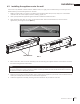
1. Remove the securing screw from the electrical cover plate located on the rear left side of the appliance.
2. Loosen the securing screw from the terminal block to remove the cord from the terminal block. KEEP 2 WIRE
JUMPERS IN THE TERMINAL BLOCK.
3. Add an electrical box connector and feed the supply wires through the 7/8” (22mm) hole from the terminal
block.
4. Insert White (N) wire from power supply to the designated (N) slots in the terminal block. Secure by tightening
the screws on the (N) slots. ENSURE JUMPER WIRES ARE SECURED.
5. Repeat step 4 with Black (L1) and Green (G), securing them to their designated slots in the terminal block.
6. Re-install cover plate.
Leave enough wire so that the appliance can be removed from the enclosure without disconnecting the
power supply.
note:
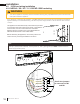
GROUND
BLACK
BLACK
BLACK
WHITE
WHITE
WIRE NUT
WALL
SWITCH
POWER
SUPPLY
MARRET
RED
RED
RED
RED
GREEN
GREEN
THERMOSTAT
(L1)
(N)
(L1)
(N)
GREEN (G)
GREEN (G)
RED (L2)
BLACK (L1)
WHITE (N)
YELLOW (N2)
YELLOW (N1)
BLACK (L1)
JUMPER
JUMPER
WHITE (N)
120V
4.5.2 NEFL42 / 50 / 60 / 74CHS 120V hardwiring
WHITE (N)
BLACK (L1)
GREEN (G)
(N)
(G)
(L1)