NEFL42CHS / NEFL50CHSMULTIPLE / NEFL60CHS / NEFL74CHS PRODUCT CODES (LEAVE BLANK IF N/A) ENGLISH NEFL42CHD / NEFL50CHD / NEFL60CHD / NEFL74CHD / NEFL100CHD FRENCH FRENCH PG.35 PG.
EN safety information ! WARNING • If equipped with a heater, this appliance can be hot when operated and can cause severe burns if contacted. • Do not operate appliance before reading and understanding operating instructions. Failure to operate appliance according to operating instructions could cause fire or injury. • Do not install damaged, incomplete or substitute components. • Do not burn wood or other materials in this appliance.
• It is normal for your electric appliance to produce noise, especially when installed in a quiet space such as a bedroom. ! WARNING safety information • To prevent a possible fire, do not block air intakes or exhaust in any manner. Do not use on soft surfaces, like a carpet, where openings may become blocked. • Always plug appliances directly into a wall outlet/receptacle. Never use an extension cord or relocatable power tap (outlet/power strip).
EN table of contents 1.0 2.0 dimensions general information 5 6 3.0 location 9 4.0 installation 10 5.0 6.0 framing - recessed installation finishing 20 21 7.0 wiring diagram 23 8.0 operation 25 9.0 maintenance 27 10.0 replacements 28 11.0 12.0 13.0 troubleshooting warranty notes 31 32 33 2.1 2.2 2.3 2.4 2.5 listing approvals general instructions rating plate information hardware list label location 3.1 3.
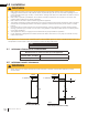
A 1.0 dimensions C A EN C H RIGHT SIDE VIEW F TOP VIEW F VIEWING AREA AREA VIEWING G B G C CORD LOCATION CORD LOCATION D B D E NOTE:NOTE: MODEL SHOWN IS NEFL32CHS MODEL SHOWN IS NEFL32CHS H D B CORD LOCATION Dimensions Model No. A B C D E F G H NEFL42CHS 44 7/16” (112.8cm) 17 5/16” (44cm) 4 1/4” (10.8cm) 15 7/8” (40.2cm) 42 1/16” (106.8cm) 40 1/4” (102.2cm) 11 1/16” (28.1cm) 3/4” (1.8cm) NEFL50CHS 52 11/16” (133.8cm) 17 5/16” (44cm) 4 1/4” (10.8cm) 15 7/8” (40.
EN general information 2.0 general information 2.1 listing approvals Model No. Net Weight Gross Weight NEFL42CHD 63.3 lbs (28.7kg) 82.7 lbs (37.5kg) NEFL50CHD 71.7 lbs (32.5kg) 94.8 lbs (43kg) NEFL60CHD 82.7 lbs (37.5kg) 109.1 lbs (49.5kg) NEFL74CHD 99.6 lbs (45.2kg) 130 lbs (59kg) NEFL100CHD 130 lbs (59kg) 167.
2.3 general information rating plate information EN The below illustration is for reference only. Refer to the appliance rating plate for accurate information. CERTIFIED UNDER CANADIAN AND AMERICAN NATIONAL STANDARD: CSA 22.2 NO. 46 AND UL 2021 / HOMOLOGUÉ SELON LES NORMES NATIONALES CANADIENNES ET AMÉRICAINES: CSA 22.2 NO. 46 UL 2021 E L P FOYER ÉLECTRIQUE. HOMOLOGUÉ POUR INSTALLATION DANS UNE CHAMBRE À COUCHER, UNE SALLE DE BAIN ET UN STUDIO. APPROPRIÉ POUR INSTALLATION DANS UNE MAISON MOBILE.
EN general information 2.5 label location Hot Surface Label (W385-2017) Do Not Cover Label (W385-2210) Front Glass Label (W385-2321) Warning Label (W385-1943) Power Cord Rating Plate Label Hardwiring Label (W385-2224 or W385-2225) Wiring Diagram Label (W385-2222 or W385-2223) Warning Label (W385-1944) 8 W415-2212 / E / 06.27.
• locating 3.0appliance location ! WARNING EN Due to high temperatures, this electric appliance should be located out of traffic. Keep combustible materials such as furniture, pillows, bedding, papers, clothes and curtains at least 36” (91.4cm) from the front of the appliance. Never locate this electric appliance where it may fall into a bathtub or other water container. Wear safety gloves and safety glasses for protection during installation and maintenance.
EN 4.0 installation installation ! WARNING • Risk of fire! The power cord must not be pinched against a sharp edge. Secure cord to avoid tripping or snagging to reduce the risk of fire, electric shock, or personal injury. Do not run cord under carpeting. Do not cover cord with throw rugs, runners, or similar items. Arrange cord away from traffic areas and where it will not be tripped over. Risk of fire! To prevent a possible fire, do not block air intake or exhaust in any manner.
4.3 installation installing the appliance onto the wall EN Due to the many different materials used on different walls, it is highly recommended that you consult your local builder before you install this appliance on the wall. 1. Select a location that is not prone to moisture and is located at least 36” (91.4cm) away from combustible materials such as curtain drapes, furniture, bedding, paper, etc. 2. Have 2 people hold the appliance against the wall to determine the final location. 3.
EN installation 7. Install 2 screws through the side wall mounting brackets to secure the appliance to the wall (FIG. 2). Wood Screw Metal Screws Side Wall Mounting Bracket FIG. 2 8. Install side panels (see “side panel installation” section). 9. Place the crystals or optional topaz glass chips and drift wood logs (CHD models only) along the media tray (see “crystal ember installation” and “optional topaz glass chips and drift wood log installation” sections). 10.
installation EN 4.3.1 side panel installation (wall mount installation only) 1. Install left and right panels (FIG. 1) by securing 4 fasteners (2 per panel) to bottom of appliance (FIG. 2). FIG. 1 4.4 FIG. 2 recessing the appliance into the wall Due to the many different materials used on different walls, it is highly recommended that you consult your local builder before you install this appliance on the wall. Select a location that is not prone to moisture and is located at least 36” (91.
EN installation 5. 6. 7. 8. Install trims (see “trim installation” section). Hold the appliance up to ensure it will fit into the framing (see “framing - recessed installation” section). Apply shims (not supplied) between the appliance and the frame. Use 4 screws to secure the appliance into the wall (FIG. 5). Do not overtighten screws. FIG. 5 9. Re-install the plastic panel holders. 10.
4.4.2 installing the appliance into a mantel ! installation DO NOT SLIDE APPLIANCE NE GLISSEZ PAS L'APPAREIL EN ! 1. Remove the front glass (see “front glass installation and removal” section). 2. Install the top and bottom brackets (not supplied). 1/4" 3. Insert the appliance into the mantel and secure it with the brackets. For appropriate mantel installation instructions, consult your authorized dealer. 4.
EN installation 4.5 120V hard wiring installation 4.5.1 NEFL42 / 50 / 60 / 74 / 100CHD 120V hardwiring ! WARNING • Turn off the appliance completely and let cool before servicing. Only a qualified service person should service and repair this electric appliance. If it is necessary to hard wire this appliance, a qualified electrician must remove the cord connection and wire the appliance directly to the household wiring. The wire and power supply breaker must be rated for 120V minimum 15 amps.
installation 1. Remove the securing screw from the electrical cover plate located on the rear left side of the appliance. 2. Loosen the securing screw from the terminal block to remove the cord from the terminal block. KEEP 2 WIRE JUMPERS IN THE TERMINAL BLOCK. 3. Add an electrical box connector and feed the supply wires through the 7/8” (22mm) hole from the terminal block. 4. Insert White (N) wire from power supply to the designated (N) slots in the terminal block.
installation 240V BLACK (L1) SUPPLY POWER JUNCTION FIREPLACE EN YELLOW (N1) (L2) from the electrical cover plate, located on the rear left REDscrew BLACK 1. Remove the securing side (L1) of the appliance. 2. Loosen the securing screw from the terminal block to remove the cord from the terminal block. (L2) RED WHITE (N) 3. Add an electrical box connector and feed the supply wires through the 7/8” (22mm) hole from the terminal block. GREEN (G) WHITE (N) 4.
installation EN (N) White, black, red, and green wires: Connect to 240V power supply. WHITE (N) YELLOW (N1) YELLOW (N2) (L1) BLACK (L1) (L2) RED (L2) (G) GREEN (G) 1. Remove the securing screw from the electrical cover plate located on the rear left side of the appliance. 2. Loosen the securing screw from the terminal block to remove the cord from the terminal block. REMOVE 2 WIRE JUMPERS IN THE TERMINAL BLOCK. 3.
EN framing 5.0 framing - recessed installation Measurements from body of appliance: 0” Sides, Back, Top FINISHING MATERIAL A A B B JUNCTION BOX (NON-LOAD BEARING) 4 1/2" 6 1/16" 4 89mm 1/2” 152mm 6 1/16” MIN MAX [89mm] [152mm] minimum for CHS minimum for CHD models models 20 Model No. A B Model No. A B NEFL42CHS 16 1/8” (41cm) 42 9/16” (108.1cm) NEFL42CHD 16 1/8” (41cm) 42 9/16” (108.1cm) NEFL50CHS 16 1/8” (41cm) 50 13/16” (129.1cm) NEFL50CHD 16 1/8” (41cm) 50 13/16” (129.
• • 6.0 finishing ! WARNING EN Power supply service must be completed prior to finishing to avoid reconstruction. Heat vents and air openings cannot be covered in any circumstances. note: Ensure to remove the 2 screws from the plastic ember bed panel before applying crystals embers and/or logs. 6.
finishing EN B1 A D C C1 Recommended drift wood log placement for NEFL60CHD A B D C1 D C Recommended drift wood log placement for NEFL74CHD A B1 D C C1 D A C1 Recommended drift wood log placement for NEFL100CHD 6.3 front glass installation and removal • ! WARNING Before the front glass is installed or removed, unplug the appliance and wait until appliance is cool to touch. Glass can be heavy and fragile so handle with care. 1.
! WARNING • 7.1 7.0 wiring diagram EN Turn off the appliance completely and let cool before servicing. Only a qualified service person should service and repair this electric appliance. NEFL42 / 50 / 60 / 74CHS wiring diagram For 74” Models For 74” Models W415-2212 / E / 06.27.
EN wiring diagram 7.2 NEFL42 / 50 / 60 / 74 / 100CHD wiring diagram For 74” and 100” Models For 74” and 100” Models note: 240V hard wiring illustrated. See “120V hard wiring installation” section for 120V hard wiring. 24 W415-2212 / E / 06.27.
8.0 operation Once the appliance has been plugged into a grounded electrical outlet, it is ready to operate. EN attention: Ensure the house circuit breakers for the power supply are turned on. In the event of a power failure, the appliance will lose its memory function and will reset to factory mode when the power returns. 8.1 operating control panel The control panel is located on the lower right-hand corner of the appliance. Power Turns the appliance on/off.
EN operation 8.2 operating remote control NEFL42 / 50 / 60 / 74 / 100CHD remote Power Turns the appliance on/off. Blue Flame Controls flame brightness. Orange Flame Yellow Flame Heater Top Light NEFL42/50/60/ 74/100CHD only Ember Bed Color Turns the heater and blower on/off. Ember Bed Brightness Timer NEFL42/50/60/ 74/100CHD only Temperature Control 26 W415-2212 / E / 06.27.18 Controls the brightness of the ember bed light.
• • • ! WARNING EN In preparation for maintenance, always disconnect the power. Allow the appliance to cool before performing any cleaning, maintenance, or relocation of the appliance. Turn controls to off and remove plug from outlet. Alternatively, turn off the house circuit breaker to appliance receptacle. Do not install replacement lamps that exceed specified maximum watts. The halogen lamps in this appliance can become extremely hot.
EN 10.0 replacements replacements ! WARNING • Failure to position the parts in accordance with this manual or failure to use only parts specifically approved with this appliance may result in property damage or personal injury. Contact your dealer for questions concerning prices and policies on replacement parts. Normally, all parts can be ordered through your Authorized dealer / distributor. For warranty replacement parts, a photocopy of the original invoice will be required to honour the claim.
replacements 10.1 NEFL42 / 50 / 60 / 74CHS EN note: Care must be taken when removing and disposing of any broken glass or damaged components. Be sure to vacuum away any broken glass from inside the appliance before operation. 2 1 3 5 4 6 7 8 11 12 17 19 20 21 22 Items may not appear exactly as illustrated. REF.
EN replacements 10.2 NEFL42 / 50 / 60 / 74 / 100CHD 2 1 3 4 5 6 7 8 11 12 17 19 20 22 21 23 Items may not appear exactly as illustrated. 30 REF.
11.0 troubleshooting ! WARNING • EN Turn off the appliance completely and let cool before servicing. Only a qualified service person should service and repair this electric appliance. symptom Dim or no flame. problem solution Flame brightness not selected. See “operation” section. Flame LEDs are burnt out. Inspect the LED and replace, if necessary. Main PCB board is burnt out. Inspect the main PCV board and replace, if necessary. Ember bed is not glowing or dimming. Brightness not selected.
EN warranty 12.0 warranty Napoleon electric appliances are manufactured under the strict Standard of the world recognized ISO 9001 : 2015 Quality Management System. Napoleon products are designed with superior components and materials and assembled by trained craftsmen who take great pride in their work.
13.0 notes notes 29.1 W415-2212 / E / 06.27.
NAPOLEON CELEBRATING OVER 40 YEARS OF HOME COMFORT PRODUCTS 7200, Route Transcanadienne, Montréal, Québec H4T 1A3 24 Napoleon Road, Barrie, Ontario, Canada L4M 0G8 214 Bayview Drive, Barrie, Ontario, Canada L4N 4Y8 103 Miller Drive, Crittenden, Kentucky, USA 41030 Phone: 1-866-820-8686 napoleonproducts.
NEFL42CHS / NEFL50CHS / NEFL60CHS / NEFL74CHS NEFL42CHD / NEFL50CHDMULTIPLE / NEFL60CHD / NEFL74CHD PRODUCT CODES/ NEFL100CHD (LEAVE BLANK IF N/A) FRANÇAIS FRANCOIS INSTRUCTIONS D’INSTALLATION ADD MANUAL TITLE ET D’OPÉRATION MD Name / Code SériesProduct Alluravision (MUST use title from Price Book) (NEFL50CHD illustré) ADD PRODUCT CODE (IF MULTIPLE, _____ ILLUSTRATED) ADD PRODUCT IMAGE CONSIGNES DE SÉCURITÉ ! AVERTISSEMENT WARNING! WARNING - KEEP BATTERIES OUT OF REACH OF CHILDREN AVER ENFANTS - SW
FR consignes de sécurité ! AVERTISSEMENT • • • • • • • • • • • • • • • • • Si équipé avec un chauffage, cet appareil peut être chaud lorsqu’il fonctionne et peut causer de graves brûlures en cas de contact. Ne faites pas fonctionner l’appareil avant d’avoir lu et compris les instructions d’utilisation. L’incapacité de respecter les instructions pourrait causer un incendie ou des blessures corporelles. N’installez pas de composants endommagés ou incomplets, ni des composants de substitution.
! AVERTISSEMENT consignes de sécurité • Pour prévenir les risques d’incendie, ne bloquez pas les entrées d’air et les sorties d’air de quelque manière que ce soit. Ne placez pas cet appareil sur une surface molle telle qu’un tapis où les ouvertures pourraient se bloquer. • Toujours brancher l’appareil directement dans une prise murale. N’utilisez pas de cordons d’alimentation ou une robinet d’alimentation relogeables (alimentation/multiprise).
FR table des matiéres 1.0 2.0 dimensions informations générales 39 40 3.0 emplacement 43 4.0 installation 44 5.0 6.0 encadrement - installation encastrée finition 54 55 7.0 schéma de câblage 57 8.0 opération 59 9.0 entretien 61 10.0 rechanges 62 11.0 12.0 guide de dépannage garantie 65 67 2.1 2.2 2.3 2.4 2.5 liste d’homologation instructions générales information sur la plaque d’homologation liste des pièces emplacement de l’étiquette 3.1 3.
A RIGHT SIDE VIEW informations générales 1.0 dimensions C A TOP VIEW F F Zone de VIEWING AREA visualisation VIEWING AREA G G C C FR D D B B E Emplacement du cordon CORD LOCATION CORD LOCATION NOTE: MODEL SHOWN IS NEFL32CHS NOTE: MODEL SHOWN IS NEFL32CHS H D B Emplacement du cordon CORD LOCATION Dimensions No.
FR informations générales 2.0 informations générales 2.
2.3 information sur la plaque d’homologation informations générales FR Cette illustration est à titre de référence seulement. Consultez la plaque d’homologation pour obtenir l’information précise. CERTIFIED UNDER CANADIAN AND AMERICAN NATIONAL STANDARD: CSA 22.2 NO. 46 AND UL 2021 / HOMOLOGUÉ SELON LES NORMES NATIONALES CANADIENNES ET AMÉRICAINES: CSA 22.2 NO. 46 UL 2021 N LO FOYER ÉLECTRIQUE. HOMOLOGUÉ POUR INSTALLATION DANS UNE CHAMBRE À COUCHER, UNE SALLE DE BAIN ET UN STUDIO.
FR informations générales 2.5 emplacement de l’étiquette L’étiquette de surface chaude (W385-2017) L’étiquette « Ne pas couvrir » (W385-2210) L’étiquette de la vitre avant (W385-2321) L’étiquette d’avertissement (W385-1943) Cordon d’alimentation L’étiquette de plaque d’homologation L’étiquette de câblage (W385-2224 ou W385-2225) L’étiquette d’avertissement (W385-1944) 42 W415-2212 / E / 06.27.
3.0 de emplacement 3.0 appareil localisation ! AVERTISSEMENT • FR En raison des températures élevées, cet appareil électrique doit être situé hors de circulation. Conservez des matériaux combustibles tels que des meubles, des coussins, des litières, des papiers, des vêtements et des rideaux à au moins 36” (91,4 cm) de l’avant de l’appareil. Ne placez jamais cet appareil électrique là où il peut tomber dans une baignoire ou un autre contenant d’eau.
FR installation 4.0 installation ! AVERTISSEMENT • Risque d’incendie! Le cordon d’alimentation ne doit pas être coincé contre une arrète vive. Fixez le cordon pour éviter les chutes ou les accrochages afin de réduire le risque d’incendie, de choc électrique ou de blessures corporelles. Ne passez pas le cordon d’alimentation sous un tapis. Ne recouvrez pas le cordon avec des carpettes, des tapis de couloir ou autres revêtements similaires.
4.3 installation installation de l’appareil sur le mur FR En raison des nombreux matériaux utilisés sur différents murs, il est fortement recommandé de consulter votre constructeur local avant d’installer cet appareil sur le mur. 1. Choisir un endroit n’est pas propice à l’humidité et se trouve à au moins 36“ (91,4 cm) des matériaux combustibles tels que rideaux, meubles, literie, papier, etc. 2. Avoir deux personnes tenir l’appareil contre le mur pour déterminer l’emplacement final. 3.
FR installation 7. Installez les 3 vis à travers les supports de montage muraux pour fixer l’appareil au mur (FIG. 2). Vis à Bois Vis Métalliques Support de Montage Mural FIG. 2 8. Installez le couvercle latéral (voir la section « installation du panneau latéral »). 9.
installation 4.3.1 installation de panneau latéral (installation murale uniquement) FR 1. Installez les panneux droit et gauche (FIG. 1) en fixant les 4 attaches (2 par panneau) au bas de l’appareil (FIG. 2). FIG. 1 4.4 FIG. 1 encastrer l’appareil dans le mur En raison des nombreux matériaux utilisés sur différents murs, il est fortement recommandé de consulter votre constructeur local avant d’installer cet appareil sur le mur.
installation 5. Installer les garnitures (voir la section « installation de garniture »). 6. Tenez l’appareil en place pour vous assurer qu’il s’insère dans le cadre (voir la section « encadrement installation encastrée »). 7. Appliquez les cales (non fourni) entre l’appareil et le cadre. 8. Utilisez 4 vis pour fixer l’appareil dans le mur (FIG. 5). Ne pas trop serrez les vis. FR FIG. 5 9. Réinstallez les supports de panneaux en plastique. 10.
4.4.2 installer l’appareil dans un manteau installation ! DO NOT SLIDE APPLIANCE NE GLISSEZ PAS L'APPAREIL ! FR 1. Retirez le verre avant (voir la section « installation et enlèvement du verre avant »). 2. Installez les supports supérieur et inférieur (non fourni). 1/4"obtenir les instructions d’installation 3. Insérez l’appareil dans le manteau et fixez-le avec les supports. Pour appropriées, consultez votre revendeur agréé. 4.
FR installation 4.5 120V installation de câblage dur 4.5.1 NEFL42 / 50 / 60 / 74 / 100CHD 120V câblage ! AVERTISSEMENT • Coupez l’alimentation électrique à l’appareil et laissez-le refroidir avant d’effectuer un entretien. Seulement un technicien de service qualifié peut effectuer l’entretien ou la réparation de cet appareil électrique. S’il est nécessaire de câbler cet appareil, un électricien qualifié doit retirer la connexion du cordon et brancher l’appareil directement au câblage du ménage.
installation blanc(N)(N) WHITE sauteur JUMPER YELLOW (N2) jaune (N) blanc(N) WHITE (N) noir(L1)(L1) BLACK noir(L1) BLACK (L1) rouge(L2) (L2) RED vert (G) GREEN (G) COURANT L’APPAREIL 120V sauteur JUMPER YELLOW (N1) jaune (N) FR SSOURCE UPPLYDE POWER JJONCTION UNCTION DE FIREPLACE 1. Retirez la vis de fixation de la plaque de recouvrement électrique située à l’arrière gauche de l’appareil. 2. Desserrez la vis de fixation du bornier pour retirer le cordon du bornier.
JUNCTION FIREPLACE 240V SUPPLY POWER BLACK (L1) installation RED (L2) BLACK (L1) (L2) de l’appareil. RED 1. Retirez la vis de WHITE fixation (N) de la plaque de recouvrement électrique située à l’arrière gauche FR 2. Desserrez la vis de fixation du bornier pour retirer le cordon du bornier. RETIRER LES SAUTEURS À 2 FILS GREEN (G) WHITE (N) DU BLOC TERMINAL. 3. Ajouter un connecteur de boîte électrique et alimenter les fils d’alimentation dans le trou WIRE NUT (G) de 7/8“ (22mm) du GREEN bornier. 4.
installation FR (N) blanc(N) WHITE (N) YELLOW (N1) jaune(N1) Fils blanc, jaune, noir, rouge et verts: Connectez-les à 240V source de courant. jaune(N2) YELLOW (N2) (L1) BLACK (L1) noir(L1) (L2) RED (L2) rouge(L2) (G) vert (G) GREEN (G) 1. Retirez la vis de fixation de la plaque de recouvrement électrique située à l’arrière gauche de l’appareil. 2. Desserrez la vis de fixation du bornier pour retirer le cordon du bornier. RETIRER 2 SORTIES DE FILS DANS LE BLOC TERMINAL. 3.
FR framing 5.0 encadrement - installation encastrée Les mesures sont prises du corps: 0” Côtés, Arrière, Haut MATÉRIAU DE FINITION A A B B JUNCTIONDE BOX BOÎTE DÉRIVATION (PALIER NON CHARGE) 4 1/2" 6 1/16" 4 89mm 1/2” 152mm 6 1/16” MIN MAX [89mm] [152mm] minimum pour les minimum pour les modèles CHS modèles CHD 54 No. de Modèle A B No.
6.0 finition ! AVERTISSEMENT • • FR Le service d’alimentation doit être complété avant de finir d’éviter la reconstruction. Les évents de chaleur et les ouvertures d’air ne peuvent être couverts en aucune circonstance. 6.1 installation de braise en cristal Le verre avant doit être retiré et l’appareil doit être sécurisé à sa place finale avant que les braises de cristal soient installées (voir la section « installation et enlèvement du verre avant »). 1.
FR finition B1 A D C C1 Emplacement de bûches de bois flotté recommandé pour NEFL60CHD A B D C1 D C Emplacement de bûches de bois flotté recommandé pour NEFL74CHD A B1 D C D C1 A C1 Emplacement de bûches de bois flotté recommandé pour NEFL100CHD 6.3 installation et enlèvement de la vitre avant ! AVERTISSEMENT • Avant d’installer ou d’enlever la vitre avant, débranchez l’appareil et attendez que l’appareil soit froid au toucher. Le verre peut être lourd et fragile. Manier avec soin.
• 7.0 Schéma schémade decâblage câblage ! AVERTISSEMENT FR Éteignez complètement l’appareil et laissez refroidir avant de procéder à l’entretien. Seul un technicien qualifié doit entretenir et réparer cet appareil électrique. Pour Modèles 74” *LED de Braise Pour Modèles 74” *Flamme LED Panneau de Contrôle Panneau de Contrôle Flamme LED LED de Braise PCB Principale Moteur CN3 Moteur de Rôtissoire Vert Noir Blanc Bloc de Dérivation LED Haut 7.
W415-2212 / E / 06.27.18 Adaptateur Chaleur Chaleur 2 1 Ventilateur2 LO Ventilateur2 HI LED Haut 18.8 LED de Braise 18.8 LED de Braise 14.
8.0 operation opération Une fois que l’appareil a été branché sur une prise électrique mise à la terre, il est prêt à fonctionner. FR attention: Assurez-vous que les disjoncteurs de la maison de l’alimentation sont allumés. En cas de panne de courant, l’appareil perd sa fonction mémoire et se réinitialise en mode d’usine lorsque l’alimentation revient. 8.1 opération du panneau de commande Le panneau de commande se trouve en bas à droite de l’appareil. Activé ou désactivé l’appareil.
FR operation 8.2 opération de la télécommande Télécommande pour les modèles NEFL42/50/60/74/100CHD Puissance Activé ou désactivé l’appareil. Flamme bleue Contrôle la luminosité de la flamme. Flamme orange Paramètres: F0 - Flamme éteinte F1 - Petite flamme F2 - Flamme moyenne F3 - Flamme lumineuse F4 - Flamme la plus brillante Flamme jaune Hauteur Lumière supérieure NEFL42/50/60/ 74/100CHD seulement 60 W415-2212 / E / 06.27.18 Couleur de lit de braise Contrôle la vitesse de la flamme.
• • • • • 9.1 • • • • • • • 9.0operation entretien ! AVERTISSEMENT FR En preparation pour l’entretien, débranchez toujours l’alimentation. Laissez l’appareil électrique refroidir avant d’effectuer tout nettoyage, entretien ou relogement de l’appareil. Éteignez les commandes et retirez la fiche de la prise ou éteignez le disjoncteur de la maison sur la prise de l’appareil. N’installez pas les lampes de remplacement qui dépassent les watts maximum spécifiés.
FR 10.0 rechanges replacements ! AVERTISSEMENT • Omettre de positionner les pièces conformément à ce manuel ou d’utiliser uniquement des pièces spécifiquement approuvées pour cet appareil peut causer des dommages matériels ou des blessures corporelles. Contactez votre détaillant pour les questions concernant les prix et la disponibilité des pièces de remplacement. Normalement, toutes les pièces peuvent être commandées chez votre détaillant autorisé.
rechanges 10.1 NEFL42 / 50 / 60 / 74CHS FR note: Des précautions doivent être prises lors de l’élimination et de l’élimination de tout verre brisé ou de composants endommagés. Assurez-vous d’aspirer tout verre brisé de l’intérieur de l’appareil avant l’opération. 1 2 4 3 5 6 7 8 11 12 17 19 20 21 22 Ces articles peuvent différer de celles illustrées. RÉF.
FR rechanges 10.2 NEFL42 / 50 / 60 / 74 / 100CHD 2 1 4 3 5 6 7 8 11 12 17 19 22 21 20 23 22 24 Ces articles peuvent différer de celles illustrées. RÉF.
! AVERTISSEMENT • 11.0 guidetroubleshooting de dépannage FR Coupez l’alimentation électrique à l’appareil et laissez-le refroidir avant d’effectuer un entretien. Seulement un technicien de service qualifié peut effectuer l’entretien ou la réparation de cet appareil électrique. symptôme problème solution La luminosité du jeu de flammes est fiable ou inexistante. Éclat de flamme n’est pas sélectionné Voir la section « opération ». Les DEL sont brûlées. Vérifiez les DEL et remplacez-les au besoin.
brûlé. FR La télécommande ne fonctionne pas. Les piles sont faibles. La chauffage s’éteint automatiquement. La température ambiante est trop élevée. L’appareil est équipé d’un thermostat intégré et s’éteindra automatiquement lorsque la température programmée sera atteinte. Il s’allumera automatiquement lorsque la température de la pièce descendra en dessous de la température programmée. Flamme ne bouge pas. Moteur calé / ne fonctionne pas correctement. Cycle de marche / arrêt.
12.0 warranty garantie Les appareils électriques Napoléon sont fabriqués conformément aux normes strictes du Système de Gestion de la Qualité mondialement reconnu ISO 9001 : 2015. Les produits Napoléon sont conçus avec des composants et des matériaux de qualité supérieure, assemblés par des artisans qualifiés qui sont fiers de leur travail.
NAPOLÉON CÉLÈBRE PLUS DE 40 ANS D’EXISTENCE CONSACRÉS À LA CONCEPTION DE PRODUITS DE CONFORT 7200, Route Transcanadienne, Montréal, Québec H4T 1A3 24 Napoleon Road, Barrie, Ontario, Canada L4M 0G8 214 Bayview Drive, Barrie, Ontario, Canada L4N 4Y8 103 Miller Drive, Crittenden, Kentucky, USA 41030 Téléphone: 1-866-820-8686 napoleonproducts.