
Allure Series Installation and Operation Manual
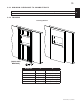
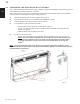

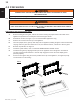
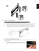
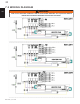
Table Of Contents

Measurements are taken from the body.
Sides, back and top 0"
5"
127mm
3 1/2"
89mm
MIN
MAX
JUNCTION
A
B
A
B
Finishing Material
3.3.1 MINIMUM CLEARANCE TO COMBUSTIBLES
3.3.2 FRAMING
(NON-LOAD
BEARING)
EN
W415-1542 / C / 01.13.16
11
MODEL NO. A B
NEFL32FH 21" (535mm) 27 13/16" (707mm)
NEFL42FH 21" (535mm) 38" (965mm)
NEFL50FH 21" (535mm) 45 15/16" (1166mm)
NEFL60FH 21" (535mm) 55 13/16" (1418mm)
NEFL72FH 21" (535mm) 67 7/8" (1725mm)
NEFL100FH 21" (535mm) 95 7/8" (2435mm)