INSTALLER: LEAVE THIS MANUAL WITH THE APPLIANCE. CONSUMER: RETAIN THIS MANUAL FOR FUTURE REFERENCE. NEVER LEAVE CHILDREN OR OTHER AT RISK INDIVIDUALS ALONE WITH THE APPLIANCE. EN INSTALLATION AND OPERATING INSTRUCTIONS CERTIFIED UNDER CANADIAN AND AMERICAN NATIONAL STANDARDS: CSA C22.
TABLE OF CONTENTS 1.0 EN 2.0 3.0 INTRODUCTION 3 1.1 1.2 1.3 1.4 1.5 4 5 5 6 6 DIMENSIONS LISTING APPROVALS GENERAL INSTRUCTIONS RATING PLATE INFORMATION LABEL LOCATION LOCATING APPLIANCE 7 2.1 2.2 7 7 UNPACKING AND TESTING APPLIANCE GROUNDING APPLIANCE INSTALLATION 3.1 3.2 3.3 3.3.1 3.3.2 4.0 5.0 6.0 7.0 8.0 9.0 MINIMUM CLEARANCE TO COMBUSTIBLES MINIMUM MANTEL CLEARANCES FRAMING HARD WIRING INSTALLATION APPLIANCE INSTALLATION 8 8 8 9 10 12 OPERATING INSTRUCTIONS 13 4.1 4.
1.0 INTRODUCTION ! • • • • • • • • • • • • • • • • • • • • • • • • • • • • • WARNING THIS APPLIANCE IS HOT WHEN OPERATED AND CAN CAUSE SEVERE BURNS IF CONTACTED. Do not operate appliance before reading and understanding operating instructions. Failure to operate appliance according to operating instructions could cause fire or injury. Risk of burns. Power to the appliance should be turned off and the appliance allowed to cool before servicing.
1.1 DIMENSIONS 24" 610mm EN 14 5/8" 371mm 21" 533mm 17 5/8" 448mm 22 1/8" 563mm 17" 432mm 11 5/8" 294mm 8 5/8" 219mm NEFB24H CEFB24HILLUSTRATED ILLUSTRATED 27" 686mm 15 3/4" 399mm 24" 610mm 18 5/8" 473mm 18" 457mm 12 3/4" 323mm 25 1/8" 639mm 9 1/2" 241mm NEFB27H CEFB27HILLUSTRATED ILLUSTRATED 29" 737mm 17 1/4" 437mm 26" 660mm NEFB29H CEFB29HILLUSTRATED ILLUSTRATED W415-1454 / C / 02.23.
1.2 LISTING APPROVALS This appliance has been tested in accordance with the CSA Standards for fixed and location-dedicated electric room appliances in the United States and Canada. If you need assistance during installation, please contact your local dealer. NOTE: This appliance must be electrically wired and grounded in accordance with local codes or, in the absence of local codes, with National Electric Code ANSI/NFPA 70-latest edition in the United States or the Canadian Electric Code, CSA C22.
1.4 RATING PLATE INFORMATION EN A M P LE CERTIFIED UNDER CANADIAN AND AMERICAN NATIONAL STANDARD: NDARD: DARD: CSA CS C 22.2 NO. 46 AND UL 2021 / HOMOLOGUÉ SELON LES NORMES NATIONALES CANADIENNES AMÉRICAINES:CSA 22.2 NO. 46 UL 2021 S ET AMÉRICAI ELECTRIC FIREPLACE. SUITABLE FOR BEDROOM AND BED-SITTING ROOM INSTALLATION. SUITABLE FOR MOBILE HOME INSTALLATION. FOYER YER À ÉLEC ÉLECTRIQUE. HOMOLOGUE POUR ÉLECT INSTALLATION INSTALLATIO ALLATIO DANS UNE CHAMBRE A COUCHER, UNE SALLE DE BAIN ET UN STUDIO.
2.0 LOCATING APPLIANCE ! WARNING EN DUE TO HIGH TEMPERATURES, THIS ELECTRIC APPLIANCE SHOULD BE LOCATED OUT OF TRAFFIC. KEEP COMBUSTIBLE MATERIALS SUCH AS FURNITURE, PILLOWS, BEDDING, PAPERS, CLOTHES AND CURTAINS AT LEAST 36" FROM THE FRONT OF THE APPLIANCE. NEVER LOCATE THIS ELECTRIC APPLIANCE WHERE IT MAY FALL INTO A BATHTUB OR OTHER WATER CONTAINER. WEAR SAFETY GLOVES AND SAFETY GLASSES FOR PROTECTION DURING INSTALLATION AND MAINTENANCE.
3.0 INSTALLATION ! WARNING RISK OF FIRE! THE POWER CORD MUST NOT BE PINCHED AGAINST A SHARP EDGE. SECURE CORD TO AVOID TRIPPING OR SNAGGING TO REDUCE THE RISK OF FIRE, ELECTRIC SHOCK OR PERSONAL INJURY. DO NOT RUN CORD UNDER CARPETING. DO NOT COVER CORD WITH THROW RUGS, RUNNERS OR THE LIKE. ARRANGE CORD AWAY FROM TRAFFIC AREAS AND WHERE IT WILL NOT BE TRIPPED OVER. EN RISK OF FIRE! TO PREVENT A POSSIBLE FIRE, DO NOT BLOCK AIR INTAKE OR EXHAUST IN ANY MANNER.
3.3 FRAMING Prepare rough in framing following the recommended dimensions in Figure 1. For the corner rough in framing, follow the recommended dimension in Figure 2. Select a location that is not prone to moisture and is located at least 36" (914mm) away from combustible materials such as curtain drapes, furniture, bedding, paper etc. Fig. 2 Fig.
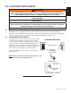
3.3.1 HARD WIRING INSTALLATION ! EN WARNING TURN OFF THE APPLIANCE COMPLETELY AND LET COOL BEFORE SERVICING. ONLY A QUALIFIED SERVICE PERSON SHOULD SERVICE AND REPAIR THIS ELECTRIC APPLIANCE. HARD WIRING CONNECTION If it is necessary to hard wire this appliance, a qualified electrician must remove the cord connection, and wire the appliance directly to the household wiring. The wire and power supply breaker must rated for 120V minimum 15 Amps.
A. Remove the securing screw from the electrical cover plate, located on the right hand side of the fireplace. B. Add an electrical box connector and feed the supply wires through the 7/8" (22mm) hole. C. Separate the black, white and green wires that have the wire nuts on them. D. Remove the wire nuts and secure the black wire (power L1) to the black (power L1) lead of the power supply. Connect the white wire from the unit to the white (neutral) wire from the power supply.
3.3.2 APPLIANCE INSTALLATION EN NOTE: This appliance is equipped with nylon pads located on the bottom four corners. To prevent damaging the base of the mantel, carefully lift the appliance into the mantel while avoiding contact with the front edge of the mantel base. A. With two people, lift the appliance up and insert into the opening, keeping a 3/8" (9.5mm) space between the appliance and floor base in order to not scratch the floor surface.
4.0 OPERATING INSTRUCTIONS Once the appliance has been plugged into a grounded electrical outlet or hard wired to a dedicated 120V power supply, it is ready to operate. ATTENTION: Ensure the house circuit breakers for the power supply are turned on. When initially connecting the appliance into a power source the unit will perform an LED check. The unit will flash on and off for 5 seconds. 4.1 OPERATING CONTROL PANEL The Control Panel is located on the top front of the appliance.
4.2 OPERATING BY REMOTE CONTROL ! EN WARNING TO AVOID DANGER OF SUFFOCATION KEEP THE PACKAGING BAG AWAY FROM BABIES AND CHILDREN. DO NOT USE IN CRIBS, BED, CARRIAGES OR PLAY PENS. THIS BAG IS NOT A TOY. KNOT BEFORE THROWING AWAY. NOTE: When operating the remote control, it must be directed towards the front center of the appliance. A. The power button can be used to turn the appliance on/off. Pressing this button activates the power to the appliance.
5.0 FINISHING ! WARNING EN POWER SUPPLY SERVICE MUST BE COMPLETED PRIOR TO FINISHING TO AVOID RECONSTRUCTION. HEAT VENTS AND AIR OPENINGS CANNOT BE COVERED IN ANY CIRCUMSTANCES. 5.1 GLASS DOOR REMOVAL AND INSTALLATION ! WARNING FACING AND/OR FINISHING MATERIAL MUST NOT INTERFERE WITH AIR FLOW THROUGH AIR OPENINGS, LOUVRES OPENINGS, OPERATION OF LOUVRES OR DOORS OR ACCESS FOR SERVICE. OBSERVE ALL CLEARANCES WHEN APPLYING COMBUSTIBLE MATERIALS.
5.3 EN BRICK PANEL INSTALLATION AND REMOVAL (NEFB29H ONLY) A. Slide the panels into place and secure with the holding bracket. B. Ensure the brick panels are positioned appropriately in the unit and are not angled or sticking out from the unit. HOLDING BRACKET HOLDING BRACKET W415-1454 / C / 02.23.
6.0 WIRING DIAGRAM TURN OFF THE APPLIANCE COMPLETELY AND LET COOL BEFORE SERVICING. ONLY A QUALIFIED SERVICE PERSON SHOULD SERVICE AND REPAIR THIS ELECTRIC APPLIANCE.
7.0 REPLACEMENT PARTS EN Contact your dealer or the factory for questions concerning prices and policies on replacement parts. Normally all parts can be ordered through your Authorized dealer / distributor. ! FOR WARRANTY REPLACEMENT PARTS, A PHOTOCOPY OF THE FAILURE TO POSITION THE PARTS ORIGINAL INVOICE WILL BE REQUIRED TO HONOUR THE CLAIM.
1 3 2 3 9 REFLECTOR SYNCHRONOUS MOTOR REMOTE CONTROL TRANSMITTER TEMPERATURE SENSOR LOG LED EMBER BED LED W010-3145 W435-0059 G660-0004 G190-0004 G405-0012 G405-0011 DESCRIPTION G190-0006 G105-0006 G010-0084 G010-0081 10 11 12 13 15 16 17 13 14 EMBER BED FLAME LED DESCRIPTION 14 15 G750-0032 WIRE ASSEMBLY BLOWER & HEATER ASSEMBLY G010-0079 W615-0135-SER SPACER, 4PCS G190-0005 MAIN PCB BOARD PART NO. G135-0011 G405-0010 REF.
1 3 2 3 W415-1454 / C / 02.23.16 10 LOG LED REMOTE CONTROL TRANSMITTER TEMPERATURE SENSOR REFLECTOR SYNCHRONOUS MOTOR NIGHT LIGHT LED G010-0082 W435-0059 G405-0007 G660-0005 G190-0004 G405-0012 G190-0006 G105-0007 DESCRIPTION FRONT GLASS FRONT HEADER CONTROL PANEL, NEFB29H CONTROL PANEL BOARD PLASTIC FLAME PANEL PART NO.
1 3 2 3 9 10 5 6 7 8 1 2 3 4 REF. 3 11 12 8 3 13 3 9 14 15 REFLECTOR SYNCHRONOUS MOTOR NIGHT LIGHT LED BRICK PANEL KIT REMOTE CONTROL TRANSMITTER G405-0007 G010-0090 G660-0005 FRONT GLASS FRONT HEADER CONTROL PANEL, CEFB29H CONTROL PANEL BOARD PLASTIC FLAME PANEL DESCRIPTION 15 16 17 18 19 20 13 14 11 12 REF. G405-0010 G010-0079 W615-0135-SER G190-0005 G750-0032 G190-0004 G405-0011 G405-0012 G010-0083 PART NO.
8.0 TROUBLESHOOTING ! EN WARNING TURN OFF THE APPLIANCE COMPLETELY AND LET COOL BEFORE SERVICING. ONLY A QUALIFIED SERVICE PERSON SHOULD SERVICE AND REPAIR THIS ELECTRIC APPLIANCE. SYMPTOM PROBLEM TEST SOLUTION Dim or no flame Flame LED’s are burnt out Inspect the LED and replace them if necessary Main PCB Board burnt out Inspect the Main PCB Board and replace if necessary. Ember bed is not glowing or dimming Ember LED’s are burnt out Inspect the ember bed LED’s and replace if necessary.
9.0 WARRANTY NAPOLEON electric appliances are manufactured under the strict Standard of the world recognized ISO 9001 : 2008 Quality Assurance Certificate. NAPOLEON products are designed with superior components and materials and assembled by trained craftsmen who take great pride in their work. Once assembled the complete appliance is thoroughly inspected by a qualified technician before packing to ensure that you, the customer, receive the quality product that you expect from NAPOLEON.
INSTALLER: LEAVE THIS MANUAL WITH THE APPLIANCE. CONSUMER: RETAIN THIS MANUAL FOR FUTURE REFERENCE. NEVER LEAVE CHILDREN OR OTHER AT RISK INDIVIDUALS ALONE WITH THE APPLIANCE. EN INSTALLATION AND OPERATING INSTRUCTIONS CERTIFIED UNDER CANADIAN AND AMERICAN NATIONAL STANDARDS: CSA C22.
2 TABLE OF CONTENTS EN 1.0 2.0 3.0 4.0 5.0 GENERAL INFORMATION OVERVIEW 2.1 2.2 2 2 MANTEL COMPONENTS LIST HARDWARE LIST 2 3 ASSEMBLY 3.1 3.2 4 APPLIANCE INSTALLATION CARE AND MAINTENANCE 8 9 WARRANTY NOTES 10 11 NOTE: Changes, other than editorial, are denoted by a vertical line in the margin. 1.0 GENERAL INFORMATION This mantel assembly is approved for use with electric appliances only. It is not approved for use as a stand alone product or in conjunction with any other appliance. 2.
3 2.2 HARDWARE LIST 1 2 5 REF. NO. 1 2 3 4 5 6 7 3 6 4 EN 7 QUANTITY DESCRIPTION 30 FLAT HEAD SCREW (3mm X 16mm) 27 FLAT HEAD BOLT (6.35mm X 25mm) 8 SHELF PIN WITH PLASTIC 4 WOOD DOWEL (8mm x 30mm) HINGES 4 DOOR KNOB 2 ALLEN KEY 1 W415-1533 / 12.11.
4 3.0 ASSEMBLY EN NOTE: Install mantel on a level surface. Loosely secure bolts until Step 4, then tighten. This ensures the mantel is straight and level. 1 C X4 2 J E I D X4 X4 W415-1533 / 12.11.
5 3 X4 EN N M X8 4 X4 Q X3 O W415-1533 / 12.11.
6 5 EN X30 P F G 6 X8 H H W415-1533 / 12.11.
7 7 EN X4 L K W415-1533 / 12.11.
8 3.1 APPLIANCE INSTALLATION ! EN WARNING DO NOT SLIDE APPLIANCE; MANTEL OR OTHER PAINTED SURFACES MAY SCRATCH. 8 E ANC I L APP The bottom of the appliance has rivets which can scratch the painted surface of the mantel; have two people lift the appliance up and insert into the opening of the mantel. W415-1533 / 12.11.
9 3.2 CARE AND MAINTENANCE ! WARNING EN DO NOT USE ABRASIVE OR CHEMICAL CLEANERS; DISCOLOURING OR DAMAGE TO FINISH MAY RESULT. Clean mantel with a non-abrasive cloth. Clean as often as necessary. NOTE: Excessive sun exposure may cause discolouring or fading of mantel finish. W415-1533 / 12.11.
10 4.0 WARRANTY EN NAPOLEON products are designed with superior components and materials, assembled by trained craftsmen who take great pride in their work. Once assembled the complete mantel is thoroughly inspected before packing to ensure that you, the customer, receive the quality product that you expect from NAPOLEON. NAPOLEON ELECTRIC APPLIANCE MANTEL LIMITED WARRANTY NAPOLEON will provide replacement parts free of charge during the first year of limited warranty.
11 5.0 NOTES EN 44.1 W415-1533 / 12.11.
® Other Napoleon Products 'JSFQMBDF *OTFSUT t $IBSDPBM (SJMMT t (BT 'JSFQMBDFT t 8BUFSGBMMT t 8PPE 4UPWFT )FBUJOH $PPMJOH t &MFDUSJD 'JSFQMBDFT t 0VUEPPS 'JSFQMBDFT t (BT (SJMMT /BQPMFPO 3PBE #BSSJF 0OUBSJP $BOBEB - . ( #BZWJFX %SJWF #BSSJF 0OUBSJP $BOBEB - / : .JMMFS %SJWF $SJUUFOEFO ,FOUVDLZ 64" 5SBOT $BOBEB )JHIXBZ .POUSFBM 2VFCFD $BOBEB ) 5 " 'JSFQMBDFT )FBUJOH $PPMJOH DBMM t (SJMMT DBMM napoleonproducts.