
Data Sheet


© 2007 Microchip Technology Inc. DS21919E-page 15
MCP23008/MCP23S08
1.6.6 CONFIGURATION (IOCON)
REGISTER
The IOCON register contains several bits for
configuring the device:
• The Sequential Operation (SEQOP) controls the
incrementing function of the address pointer. If the
address pointer is disabled, the address pointer
does not automatically increment after each byte
is clocked during a serial transfer. This feature is
useful when it is desired to continuously poll
(read) or modify (write) a register.
• The Slew Rate (DISSLW) bit controls the slew
rate function on the SDA pin. If enabled, the SDA
slew rate will be controlled when driving from a
high to a low.
• The Hardware Address Enable (HAEN) control bit
enables/disables the hardware address pins (A1,
A0) on the MCP23S08. This bit is not used on the
MCP23008. The address pins are always enabled
on the MCP23008.
• The Open-Drain (ODR) control bit enables/
disables the INT pin for open-drain configuration.
• The Interrupt Polarity (INTPOL) control bit sets
the polarity of the INT pin. This bit is functional
only when the ODR bit is cleared, configuring the
INT pin as active push-pull.
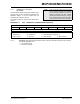
REGISTER 1-6: IOCON – I/O EXPANDER CONFIGURATION REGISTER (ADDR 0x05)
U-0 U-0 R/W-0 R/W-0 R/W-0 R/W-0 R/W-0 U-0
— —
SEQOP DISSLW HAEN ODR INTPOL
—
bit 7 bit 0
Legend:
R = Readable bit W = Writable bit U = Unimplemented bit, read as ‘0’
-n = Value at POR ‘1’ = Bit is set ‘0’ = Bit is cleared x = Bit is unknown
bit 7-6 Unimplemented: Read as ‘0’.
bit 5 SEQOP: Sequential Operation mode bit.
1 = Sequential operation disabled, address pointer does not increment.
0 = Sequential operation enabled, address pointer increments.
bit 4 DISSLW: Slew Rate control bit for SDA output.
1 = Slew rate disabled.
0 = Slew rate enabled.
bit 3 HAEN: Hardware Address Enable bit (MCP23S08 only).
Address pins are always enabled on MCP23008.
1 = Enables the MCP23S08 address pins.
0 = Disables the MCP23S08 address pins.
bit 2 ODR: This bit configures the INT pin as an open-drain output.
1 = Open-drain output (overrides the INTPOL bit).
0 = Active driver output (INTPOL bit sets the polarity).
bit 1 INTPOL: This bit sets the polarity of the INT output pin.
1 = Active-high.
0 = Active-low.
bit 0 Unimplemented: Read as ‘0’.