PCA9685 16-channel, 12-bit PWM Fm+ I2C-bus LED controller Rev. 4 — 16 April 2015 Product data sheet 1. General description The PCA9685 is an I2C-bus controlled 16-channel LED controller optimized for Red/Green/Blue/Amber (RGBA) color backlighting applications.
PCA9685 NXP Semiconductors 16-channel, 12-bit PWM Fm+ I2C-bus LED controller The active LOW Output Enable input pin (OE) allows asynchronous control of the LED outputs and can be used to set all the outputs to a defined I2C-bus programmable logic state. The OE can also be used to externally ‘pulse width modulate’ the outputs, which is useful when multiple devices need to be dimmed or blinked together using software control.
PCA9685 NXP Semiconductors 16-channel, 12-bit PWM Fm+ I2C-bus LED controller 25 MHz typical internal oscillator requires no external components External 50 MHz (max.) clock input Internal power-on reset Noise filter on SDA/SCL inputs Edge rate control on outputs No output glitches on power-up Supports hot insertion Low standby current Operating power supply voltage range of 2.3 V to 5.5 V 5.
PCA9685 NXP Semiconductors 16-channel, 12-bit PWM Fm+ I2C-bus LED controller 4. Ordering information Table 1. Ordering information Type number Topside mark Package Name Description Version PCA9685PW PCA9685PW TSSOP28 plastic thin shrink small outline package; 28 leads; body width 4.4 mm SOT361-1 PCA9685PW/Q900[1] PCA9685PW TSSOP28 plastic thin shrink small outline package; 28 leads; body width 4.
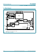
PCA9685 NXP Semiconductors 16-channel, 12-bit PWM Fm+ I2C-bus LED controller 5. Block diagram A0 A1 A2 A3 A4 A5 PCA9685 SCL INPUT FILTER SDA I2C-BUS CONTROL POWER-ON RESET VDD VDD VSS LED STATE SELECT REGISTER PRESCALE 25 MHz OSCILLATOR EXTCLK PWM REGISTER X BRIGHTNESS CONTROL LEDn MUX/ CONTROL CLOCK SWITCH '0' – permanently OFF '1' – permanently ON OE 002aac824 Remark: Only one LED output shown for clarity. Fig 1.
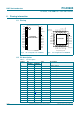
PCA9685 NXP Semiconductors 16-channel, 12-bit PWM Fm+ I2C-bus LED controller 6. Pinning information LED2 8 LED3 9 20 LED13 LED4 10 19 LED12 LED5 11 18 LED11 LED6 12 17 LED10 LED7 13 16 LED9 VSS 14 15 LED8 PCA9685PW PCA9685PW/Q900 22 LED15 21 LED14 1 21 A5 A4 2 20 OE LED0 3 LED1 4 LED2 5 17 LED13 LED3 6 16 LED12 LED4 7 15 LED11 19 LED15 PCA9685BS 18 LED14 002aad236 Transparent top view 002aac825 Fig 2.
PCA9685 NXP Semiconductors 16-channel, 12-bit PWM Fm+ I2C-bus LED controller Table 3.
PCA9685 NXP Semiconductors 16-channel, 12-bit PWM Fm+ I2C-bus LED controller • PCA9564 (0000 000) or PCA9665 (1110 000) slave address which is active on start-up • ‘reserved for future use’ I2C-bus addresses (0000 011, 1111 1XX) • slave devices that use the 10-bit addressing scheme (1111 0XX) • slave devices that are designed to respond to the General Call address (0000 000) which is used as the software reset address • High-speed mode (Hs-mode) master code (0000 1XX) slave address 1 fixed Fig 4.
PCA9685 NXP Semiconductors 16-channel, 12-bit PWM Fm+ I2C-bus LED controller 7.1.4 Software Reset I2C-bus address The address shown in Figure 5 is used when a reset of the PCA9685 needs to be performed by the master. The Software Reset address (SWRST Call) must be used with R/W = logic 0. If R/W = logic 1, the PCA9685 does not acknowledge the SWRST. See Section 7.6 “Software reset” for more detail. R/W 0 0 0 0 0 1 1 0 002aab416 Fig 5.
PCA9685 NXP Semiconductors 16-channel, 12-bit PWM Fm+ I2C-bus LED controller 7.3 Register definitions Table 4.
PCA9685 NXP Semiconductors 16-channel, 12-bit PWM Fm+ I2C-bus LED controller Table 4.
PCA9685 NXP Semiconductors 16-channel, 12-bit PWM Fm+ I2C-bus LED controller Table 4.
PCA9685 NXP Semiconductors 16-channel, 12-bit PWM Fm+ I2C-bus LED controller Table 4.
PCA9685 NXP Semiconductors 16-channel, 12-bit PWM Fm+ I2C-bus LED controller 7.3.1 Mode register 1, MODE1 Table 5. MODE1 - Mode register 1 (address 00h) bit description Legend: * default value. Bit Symbol Access Value 7 RESTART R Shows state of RESTART logic. See Section 7.3.1.1 for detail. W User writes logic 1 to this bit to clear it to logic 0. A user write of logic 0 will have no effect. See Section 7.3.1.1 for detail. 0* 1 6 EXTCLK R/W Description Restart disabled. Restart enabled.
PCA9685 NXP Semiconductors 16-channel, 12-bit PWM Fm+ I2C-bus LED controller 7.3.1.1 Restart mode If the PCA9685 is operating and the user decides to put the chip to sleep (setting MODE1 bit 4) without stopping any of the PWM channels, the RESTART bit (MODE1 bit 7) will be set to logic 1 at the end of the PWM refresh cycle. The contents of each PWM register are held valid when the clock is off. To restart all of the previously active PWM channels with a few I2C-bus cycles do the following steps: 1.
PCA9685 NXP Semiconductors 16-channel, 12-bit PWM Fm+ I2C-bus LED controller 7.3.2 Mode register 2, MODE2 Table 6. MODE2 - Mode register 2 (address 01h) bit description Legend: * default value. Bit Symbol Access Value 7 to 5 - read only 000* reserved 4 INVRT[1] R/W 0* Output logic state not inverted. Value to use when external driver used. Applicable when OE = 0. 1 Output logic state inverted. Value to use when no external driver used. Applicable when OE = 0.
PCA9685 NXP Semiconductors 16-channel, 12-bit PWM Fm+ I2C-bus LED controller Example 1: (assumes that the LED0 output is used and (delay time) + (PWM duty cycle) 100 %) Delay time = 10 %; PWM duty cycle = 20 % (LED on time = 20 %; LED off time = 80 %). Delay time = 10 % = 409.6 ~ 410 counts = 19Ah. Since the counter starts at 0 and ends at 4095, we will subtract 1, so delay time = 199h counts. LED0_ON_H = 1h; LED0_ON_L = 99h (LED start turn on after this delay count to 409) LED on time = 20 % = 819.
PCA9685 NXP Semiconductors 16-channel, 12-bit PWM Fm+ I2C-bus LED controller STOP 0 4095 0 4095 0 4095 0 example 1 LEDn_ON LEDn_OFF 511 511 511 3071 3071 3071 example 2 LEDn_ON LEDn_OFF 2047 2047 767 2047 767 example 3 LEDn_ON example 4 1023 off LEDn_ON LEDn_OFF 1023 1023 002aad193 Example 1: LEDn_ON (511) < LEDn_OFF (3071) Example 2: LEDn_ON (2047) > LEDn_OFF (767) Example 3: LEDn_ON[12] = 1; LEDn_ON[11:0] = 1022; LEDn_OFF[12] = 0; LEDn_OFF[11:0] = don’t care Example 4: LEDn_ON[12]
PCA9685 NXP Semiconductors 16-channel, 12-bit PWM Fm+ I2C-bus LED controller STOP 0 4095 0 4095 0 register(s) updated in this cycle 4095 0 output(s) updated in this cycle example 1 LEDn_ON LEDn_OFF 511 511 511 3071 1023 1023 3071 767 1023 767 1023 example 2 LEDn_ON LEDn_OFF 511 example 3 LEDn_ON LEDn_OFF 511 3071 3071 example 4 LEDn_ON LEDn_OFF 1023 off 511 3071 002aad194 Example 1: LEDn_ON unchanged and LEDn_OFF decreased. Example 2: LEDn_ON increased and LEDn_OFF decreased.
xxxxxxxxxxxxxxxxxxxxx xxxxxxxxxxxxxxxxxxxxxxxxxx xxxxxxx x x x xxxxxxxxxxxxxxxxxxxxxxxxxxxxxx xxxxxxxxxxxxxxxxxxx xx xx xxxxx xxxxxxxxxxxxxxxxxxxxxxxxxxx xxxxxxxxxxxxxxxxxxx xxxxxx xxxxxxxxxxxxxxxxxxxxxxxxxxxxxxxxxxx xxxxxxxxxxxx x x xxxxxxxxxxxxxxxxxxxxx xxxxxxxxxxxxxxxxxxxxxxxxxxxxxx xxxxx xxxxxxxxxxxxxxxxxxxxxxxxxxxxxxxxxxxxxxxxxxxxxxxxxx xxxxxxxx xxxxxxxxxxxxxxxxxxxxxxxxx xxxxxxxxxxxxxxxxxxxx xxx 4095 0 4095 0 4095 0 NXP Semiconductors PCA9685 Product data sheet STOP 0 4095 0 output(s) updated
PCA9685 NXP Semiconductors 16-channel, 12-bit PWM Fm+ I2C-bus LED controller Table 7. LED_ON, LED_OFF control registers (address 06h to 45h) bit description Legend: * default value.
PCA9685 NXP Semiconductors 16-channel, 12-bit PWM Fm+ I2C-bus LED controller Table 7. LED_ON, LED_OFF control registers (address 06h to 45h) bit description …continued Legend: * default value.
PCA9685 NXP Semiconductors 16-channel, 12-bit PWM Fm+ I2C-bus LED controller Table 7. LED_ON, LED_OFF control registers (address 06h to 45h) bit description …continued Legend: * default value.
PCA9685 NXP Semiconductors 16-channel, 12-bit PWM Fm+ I2C-bus LED controller Table 7. LED_ON, LED_OFF control registers (address 06h to 45h) bit description …continued Legend: * default value.
PCA9685 NXP Semiconductors 16-channel, 12-bit PWM Fm+ I2C-bus LED controller 7.3.4 ALL_LED_ON and ALL_LED_OFF control The ALL_LED_ON and ALL_LED_OFF registers allow just four I2C-bus write sequences to fill all the ON and OFF registers with the same patterns. Table 8. ALL_LED_ON and ALL_LED_OFF control registers (address FAh to FEh) bit description Legend: * default value.
PCA9685 NXP Semiconductors 16-channel, 12-bit PWM Fm+ I2C-bus LED controller 7.3.6 SUBADR1 to SUBADR3, I2C-bus subaddress 1 to 3 SUBADR1 to SUBADR3 - I2C-bus subaddress registers 0 to 3 (address 02h to 04h) bit description Legend: * default value. Table 9.
PCA9685 NXP Semiconductors 16-channel, 12-bit PWM Fm+ I2C-bus LED controller 7.4 Active LOW output enable input The active LOW output enable (OE) pin, allows to enable or disable all the LED outputs at the same time. • When a LOW level is applied to OE pin, all the LED outputs are enabled and follow the output state defined in the LEDn_ON and LEDn_OFF registers with the polarity defined by INVRT bit (MODE2 register).
PCA9685 NXP Semiconductors 16-channel, 12-bit PWM Fm+ I2C-bus LED controller 7.6 Software reset The Software Reset Call (SWRST Call) allows all the devices in the I2C-bus to be reset to the power-up state value through a specific formatted I2C-bus command. To be performed correctly, it implies that the I2C-bus is functional and that there is no device hanging the bus. The SWRST Call function is defined as the following: 1. A START command is sent by the I2C-bus master. 2.
PCA9685 NXP Semiconductors 16-channel, 12-bit PWM Fm+ I2C-bus LED controller 7.7 Using the PCA9685 with and without external drivers The PCA9685 LED output drivers are 5.5 V only tolerant and can sink up to 25 mA at 5 V. If the device needs to drive LEDs to a higher voltage and/or higher current, use of an external driver is required. • INVRT bit (MODE2 register) can be used to keep the LED PWM control firmware the same independently of the type of external driver.
PCA9685 NXP Semiconductors 16-channel, 12-bit PWM Fm+ I2C-bus LED controller 8. Characteristics of the I2C-bus The I2C-bus is for 2-way, 2-line communication between different ICs or modules. The two lines are a serial data line (SDA) and a serial clock line (SCL). Both lines must be connected to a positive supply via a pull-up resistor when connected to the output stages of a device. Data transfer may be initiated only when the bus is not busy. 8.
PCA9685 NXP Semiconductors 16-channel, 12-bit PWM Fm+ I2C-bus LED controller SDA SCL MASTER TRANSMITTER/ RECEIVER SLAVE RECEIVER SLAVE TRANSMITTER/ RECEIVER MASTER TRANSMITTER MASTER TRANSMITTER/ RECEIVER I2C-BUS MULTIPLEXER SLAVE 002aaa966 Fig 18. System configuration 8.3 Acknowledge The number of data bytes transferred between the START and the STOP conditions from transmitter to receiver is not limited. Each byte of eight bits is followed by one acknowledge bit.
PCA9685 NXP Semiconductors 16-channel, 12-bit PWM Fm+ I2C-bus LED controller 9. Bus transactions slave address S data for register D[7:0](1) control register 1 A5 A4 A3 A2 A1 A0 0 START condition R/W A D7 D6 D5 D4 D3 D2 D1 D0 A acknowledge from slave A acknowledge from slave P acknowledge from slave STOP condition 002aac829 (1) See Table 4 for register definition. Fig 20.
PCA9685 NXP Semiconductors 16-channel, 12-bit PWM Fm+ I2C-bus LED controller slave address S control register = MODE1 register 1 A5 A4 A3 A2 A1 A0 0 START condition A R/W 0 0 0 0 0 acknowledge from slave 0 0 A 1 acknowledge from slave slave address (cont.) 0 MODE1 register AI bit set data from MODE1 Sr 1 A5 A4 A3 A2 A1 A0 1 ReSTART condition R/W acknowledge from slave data from MODE2 A acknowledge from slave (cont.
PCA9685 NXP Semiconductors 16-channel, 12-bit PWM Fm+ I2C-bus LED controller slave address sequence (A)(1) S control register 1 A5 A4 A3 A2 A1 A0 0 START condition A 0 0 0 0 0 0 data for MODE1 register 0 0 A 0 0 0 0 0 1 0 1 ALLCALLADR register selection R/W LEDALLCALL I2C-bus address 1 0 1 0 1 0 1 START condition A 1 1 0 0 0 0 0 0 0 0 A ALL_LED_ON_H control register 0 1 1 1 0 1 1 1 A enable ALL CALL acknowledge from slave 1 0 1 0 1 acknowledge f
PCA9685 NXP Semiconductors 16-channel, 12-bit PWM Fm+ I2C-bus LED controller 10. Application design-in information 5V VDD = 2.5 V, 3.3 V or 5.0 V (1) I2C-BUS/SMBus MASTER SDA (1) 12 V 10 kΩ(2) VDD SDA LED0 SCL SCL LED1 OE OE LED2 LED3 5V 12 V PCA9685 LED4 LED5 LED6 LED7 5V 12 V LED8 LED9 LED10 LED11 5V EXTCLK 12 V A0 A1 A2 A3 A4 LED12 LED13 A5 LED14 VSS LED15 002aac827 I2C-bus address = 1010 101x. All 16 of the LEDn outputs configurable as either open-drain or totem pole.
PCA9685 NXP Semiconductors 16-channel, 12-bit PWM Fm+ I2C-bus LED controller Question 1: What kind of edge rate control is there on the outputs? • The typical edge rates depend on the output configuration, supply voltage, and the applied load. The outputs can be configured as either open-drain NMOS or totem pole outputs. If the customer is using the part to directly drive LEDs, they should be using it in an open-drain NMOS, if they are concerned about the maximum ISS and ground bounce.
PCA9685 NXP Semiconductors 16-channel, 12-bit PWM Fm+ I2C-bus LED controller LED supply VIN CONSTANT CURRENT SWITCH MODE REGULATOR FB OUT Iconstant LIGHT SENSOR VDD = 2.5 V, 3.3 V or 5.0 V (1) LED string (1) 10 kΩ(2) ASIC/MICRO VDD SDA SDA LED0 SCL SCL LED1 Rsense LED2 OE OE LED3 PCA9685 LED4 LED5 LED6 LED7 EXTCLK LED8 LED9 LED10 LED11 A0 A1 A2 A3 A4 LED12 LED13 A5 LED14 VSS LED15 002aac828 I2C-bus address = 1010 101x.
PCA9685 NXP Semiconductors 16-channel, 12-bit PWM Fm+ I2C-bus LED controller 11. Limiting values Table 13. Limiting values In accordance with the Absolute Maximum Rating System (IEC 60134). Symbol Parameter VDD Conditions Min Max Unit supply voltage 0.5 +6.0 V VI/O voltage on an input/output pin VSS 0.5 5.
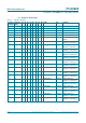
PCA9685 NXP Semiconductors 16-channel, 12-bit PWM Fm+ I2C-bus LED controller Table 14. Static characteristics …continued VDD = 2.3 V to 5.5 V; VSS = 0 V; Tamb = 40 C to +85 C; unless otherwise specified. Symbol Parameter Conditions Min Typ Max Unit Address inputs; OE input; EXTCLK VIL LOW-level input voltage 0.5 - +0.3VDD V VIH HIGH-level input voltage 0.7VDD - 5.5 V ILI input leakage current 1 - +1 A Ci input capacitance - 3 5 pF [1] VDD must be lowered to 0.
xxxxxxxxxxxxxxxxxxxxx xxxxxxxxxxxxxxxxxxxxxxxxxx xxxxxxx x x x xxxxxxxxxxxxxxxxxxxxxxxxxxxxxx xxxxxxxxxxxxxxxxxxx xx xx xxxxx xxxxxxxxxxxxxxxxxxxxxxxxxxx xxxxxxxxxxxxxxxxxxx xxxxxx xxxxxxxxxxxxxxxxxxxxxxxxxxxxxxxxxxx xxxxxxxxxxxx x x xxxxxxxxxxxxxxxxxxxxx xxxxxxxxxxxxxxxxxxxxxxxxxxxxxx xxxxx xxxxxxxxxxxxxxxxxxxxxxxxxxxxxxxxxxxxxxxxxxxxxxxxxx xxxxxxxx xxxxxxxxxxxxxxxxxxxxxxxxx xxxxxxxxxxxxxxxxxxxx xxx NXP Semiconductors PCA9685 Product data sheet 13. Dynamic characteristics Table 15.
xxxxxxxxxxxxxxxxxxxxx xxxxxxxxxxxxxxxxxxxxxxxxxx xxxxxxx x x x xxxxxxxxxxxxxxxxxxxxxxxxxxxxxx xxxxxxxxxxxxxxxxxxx xx xx xxxxx xxxxxxxxxxxxxxxxxxxxxxxxxxx xxxxxxxxxxxxxxxxxxx xxxxxx xxxxxxxxxxxxxxxxxxxxxxxxxxxxxxxxxxx xxxxxxxxxxxx x x xxxxxxxxxxxxxxxxxxxxx xxxxxxxxxxxxxxxxxxxxxxxxxxxxxx xxxxx xxxxxxxxxxxxxxxxxxxxxxxxxxxxxxxxxxxxxxxxxxxxxxxxxx xxxxxxxx xxxxxxxxxxxxxxxxxxxxxxxxx xxxxxxxxxxxxxxxxxxxx xxx Dynamic characteristics …continued Symbol Parameter Conditions OE to LEDn; OUTNE[1:0] = 10 or 11 in MODE
PCA9685 NXP Semiconductors 16-channel, 12-bit PWM Fm+ I2C-bus LED controller 0.7 × V DA 0.3 × V tr tBUF tf tHD;STA tSP tLOW 0.7 × V CL 0.3 × V tHD;STA P tSU;STA tHD;DAT S tHIGH tSU;DAT tSU;STO Sr P 002aaa9 Fig 31. Definition of timing protocol START condition (S) tSU;STA bit 7 MSB (A7) tLOW bit 6 (A6) tHIGH bit 1 (D1) acknowledge (A) bit 0 (D0) STOP condition (P) 1 / fSCL 0.7 × VDD SCL 0.3 × VDD tBUF tf tr 0.7 × VDD SDA 0.
PCA9685 NXP Semiconductors 16-channel, 12-bit PWM Fm+ I2C-bus LED controller 14. Test information VDD VI PULSE GENERATOR RL 500 Ω VO VDD open VSS DUT CL 50 pF RT 002aab880 RL = Load resistor for LEDn. CL = Load capacitance includes jig and probe capacitance. RT = Termination resistance should be equal to the output impedance Zo of the pulse generators. Fig 34.
PCA9685 NXP Semiconductors 16-channel, 12-bit PWM Fm+ I2C-bus LED controller 15. Package outline TSSOP28: plastic thin shrink small outline package; 28 leads; body width 4.4 mm D SOT361-1 E A X c HE y v M A Z 15 28 Q A2 (A 3) A1 pin 1 index A θ Lp 1 L 14 detail X w M bp e 0 2.5 5 mm scale DIMENSIONS (mm are the original dimensions) UNIT A max. A1 A2 A3 bp c D (1) E (2) e HE L Lp Q v w y Z (1) θ mm 1.1 0.15 0.05 0.95 0.80 0.25 0.30 0.19 0.2 0.1 9.8 9.
PCA9685 NXP Semiconductors 16-channel, 12-bit PWM Fm+ I2C-bus LED controller HVQFN28: plastic thermal enhanced very thin quad flat package; no leads; 28 terminals; body 6 x 6 x 0.85 mm B D SOT788-1 A terminal 1 index area A A1 E c detail X C e1 e 14 y y1 C v M C A B w M C b 8 L 7 15 e e2 Eh 21 1 terminal 1 index area 28 22 X Dh 0 2.5 5 mm scale DIMENSIONS (mm are the original dimensions) UNIT A(1) max. A1 b c D (1) Dh E (1) Eh e e1 e2 L v w y y1 mm 1 0.
PCA9685 NXP Semiconductors 16-channel, 12-bit PWM Fm+ I2C-bus LED controller 16. Handling information All input and output pins are protected against ElectroStatic Discharge (ESD) under normal handling. When handling ensure that the appropriate precautions are taken as described in JESD625-A or equivalent standards. 17. Soldering of SMD packages This text provides a very brief insight into a complex technology.
PCA9685 NXP Semiconductors 16-channel, 12-bit PWM Fm+ I2C-bus LED controller • Process issues, such as application of adhesive and flux, clinching of leads, board transport, the solder wave parameters, and the time during which components are exposed to the wave • Solder bath specifications, including temperature and impurities 17.
PCA9685 NXP Semiconductors 16-channel, 12-bit PWM Fm+ I2C-bus LED controller maximum peak temperature = MSL limit, damage level temperature minimum peak temperature = minimum soldering temperature peak temperature time 001aac844 MSL: Moisture Sensitivity Level Fig 38. Temperature profiles for large and small components For further information on temperature profiles, refer to Application Note AN10365 “Surface mount reflow soldering description”. 18. Abbreviations Table 19.
PCA9685 NXP Semiconductors 16-channel, 12-bit PWM Fm+ I2C-bus LED controller 19. Revision history Table 20. Revision history Document ID Release date Data sheet status Change notice Supersedes PCA9685 v.4 20150416 Product data sheet - PCA9685 v.3 Modifications: • • Changed programmable frequency to “24 Hz to 1526 Hz” throughout Minor edits to text and figures to provide clarity regarding cycle count throughout PCA9685 v.3 20100902 Product data sheet - PCA9685 v.2 PCA9685 v.
PCA9685 NXP Semiconductors 16-channel, 12-bit PWM Fm+ I2C-bus LED controller 20. Legal information 20.1 Data sheet status Document status[1][2] Product status[3] Definition Objective [short] data sheet Development This document contains data from the objective specification for product development. Preliminary [short] data sheet Qualification This document contains data from the preliminary specification. Product [short] data sheet Production This document contains the product specification.
PCA9685 NXP Semiconductors 16-channel, 12-bit PWM Fm+ I2C-bus LED controller Export control — This document as well as the item(s) described herein may be subject to export control regulations. Export might require a prior authorization from competent authorities. Non-automotive qualified products — Unless this data sheet expressly states that this specific NXP Semiconductors product is automotive qualified, the product is not suitable for automotive use.
PCA9685 NXP Semiconductors 16-channel, 12-bit PWM Fm+ I2C-bus LED controller 22. Contents 1 2 3 4 4.1 5 6 6.1 6.2 7 7.1 7.1.1 7.1.2 7.1.3 7.1.4 7.2 7.3 7.3.1 7.3.1.1 7.3.2 7.3.3 7.3.4 7.3.5 7.3.6 7.3.7 7.4 7.5 7.6 7.7 8 8.1 8.1.1 8.2 8.3 9 10 11 12 13 14 15 16 17 General description . . . . . . . . . . . . . . . . . . . . . . 1 Features and benefits . . . . . . . . . . . . . . . . . . . . 2 Applications . . . . . . . . . . . . . . . . . . . . . . . . . . . . 3 Ordering information . . . . . . . . . . .