
Computer Hardware User Manual


Chapter 4 Signal Connections
AT-MIO/AI E Series User Manual 4-40
National Instruments Corporation
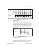
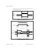
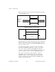
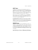
Figures 4-23 and 4-24 show the input and output timing requirements
for the CONVERT* signal.
Figure 4-23. CONVERT* Input Signal Timing
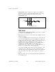
Figure 4-24. CONVERT* Output Signal Timing
The ADC switches to hold mode within 60 ns of the selected edge. This
hold-mode delay time is a function of temperature and does not vary
from one conversion to the next. Separate the CONVERT* pulses by at
least one conversion period.
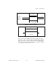
The sample interval counter on the AT E Series board normally
generates the CONVERT* signal unless you select some external
source. The counter is started by the STARTSCAN signal and
continues to count down and reload itself until the scan is finished. It
then reloads itself in readiness for the next STARTSCAN pulse.
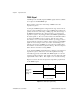
A/D conversions generated by either an internal or external
CONVERT* signal are inhibited unless they occur within a data
acquisition sequence. Scans occurring within a data acquisition
sequence may be gated by either the hardware (AIGATE) signal or
software command register gate.
Rising-edge
polarity
Falling-edge
polarity
t
w
t
w
= 10 ns minimum
t
w
t
w
= 50-100 ns