
User's Manual
Register-Level Programming Chapter 4
Lab-NB User Manual 4-52 © National Instruments Corporation
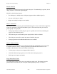
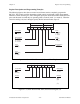
channel 3, channel 2, channel 1, channel 0, channel 3, channel 2, channel 1, channel 0,
channel 3, and so on.
Note: Select the analog input channel and gain in the following order:
1. Write the configuration value indicating the highest channel number in the scan
sequence, the gain, and the input polarity to the A/D Configuration Register. The
SCANEN bit must be cleared during this first write to the A/D Configuration
Register.
2. Write the same configuration value again to the A/D Configuration Register. The
SCANEN bit, however, must be set during the second write to the A/D
Configuration Register.
Scanning can be enabled in either controlled or freerun acquisition mode. Use either counter A0
or EXTCONV* to control the scanning interval.
Interrupt Programming for the Analog Input Circuitry
Use interrupts to service the A/D FIFO during a DAQ operation. To use the conversion
interrupt, set the ADCINTEN bit in the Interrupt Control Register. If this bit is set, an interrupt
is generated whenever the DAVAIL bit in the Status Register is set. This interrupt condition is
cleared when the A/D FIFO is emptied by reading its contents.
Programming the Analog Output Circuitry
The analog output circuitry on the Lab-NB uses double-buffered DACs. Thus, the voltage at the
output pins (pins DAC0OUT and DAC1OUT on the Lab-NB I/O connector) does not update
immediately with each write to the DAC Data Registers. The analog output can be updated in
synchronization with counter A2 output or the external update control signal EXTUPDATE*.
This ability is useful for waveform generation applications because the timed update pulses
eliminate the timing jitter associated with software writes to the DAC Data Registers.
The voltage at the analog output circuitry pins (pins DAC0OUT and DAC1OUT on the Lab-NB
I/O connector) is controlled by loading the DAC in the analog output channel with a 12-bit
digital code. The DACs can be loaded by writing the digital code to the DAC0 and DAC1 Data
Registers. Writing to the DAC0 Data Register loads DAC0, and writing to the DAC1 Data
Register loads DAC1. Writing to the DAC0 and DAC1 Data Registers loads both DAC0 and
DAC1 simultaneously with the same digital code. The analog output on pins DAC0OUT or
DAC1OUT can be updated in one of three ways: immediately when the DAC0 Data Register or
the DAC1 Data Register is written to, when a low level is detected on the EXTUPDATE* pin, or
when a low level is detected on counter A’s output (OUTA2). The TMRWGN bits in the DAC
Configuration Register determine which update method is used. If TMRWGN0 is set high, the
analog output from DAC0 is updated when a low level is detected on either EXTUPDATE* or
OUTA2. If TMRWGN0 is set low, the analog output from DAC0 is updated as soon as the
DAC0 Data Register is written to. TMRWGN1 controls the updating of DAC1 analog output in
a similar manner.
The output voltage generated from the digital code depends on the configuration, unipolar or
bipolar, of the associated analog output channel. Unipolar or bipolar configuration is determined