
User's Manual

Register-Level Programming Chapter 4
Lab-NB User Manual 4-54 © National Instruments Corporation
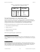
Table 4-6. Analog Output Voltage Versus Digital Code
(Bipolar Mode, Two’s Complement Coding)
Digital Code Voltage Output
(Decimal) (Hex) (V
ref
= 10 V)
-2,048 F800 -5.0 V
-1,024 FC00 -2.5 V
0 0000 0.0 V
1,024 0400 2.5 V
2,047 07FF 4.9976 V
Interrupt Programming for the Analog Output Circuitry
Interrupts can be used for writing successive values in a sequence to the DAC Data Registers
during a waveform generation operation. The TMRINTEN bit in the Interrupt Control Registers
enables and disables counter A2 and EXTUPDATE* driven interrupts. See Chapter 2,
Configuration and Installation, for timing requirements on the EXTUPDATE* signal.
The following programming steps are required for waveform generation using interrupts:
1. Set up the DAC Configuration Register.
2. Program counter A2.
3. Install an interrupt service routine.
4. Enable timer interrupts.
Each of these programming steps is explained below.
1. Set up the DAC Configuration Register.
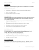
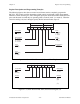
The TMRWGN0 bit must be set high for enabling OUTA2 or EXTUPDATE* driven updates on
DAC0. TMRWGN1 bit must be set high for enabling OUTA2 or EXTUPDATE* driven updates
on DAC1.
2. Program counter A2.
If EXTUPDATE* is being used to update the DACs, counter A2 output (OUTA2) must be set
high by writing B8(hex) to the Counter A Mode Register. If OUTA2 is being used to update the
DACs, EXTUPDATE* must be left unconnected or driven to a TTL-high level. Counter A2
must be programmed in mode 2 with the appropriate update interval.