
User's Manual

Chapter 4 Register-Level Programming
© National Instruments Corporation 4-55 Lab-NB User Manual
3. Install an interrupt service routine.
You must install an interrupt service routine for the slot containing the Lab-NB. Consult the
Inside Macintosh manual for information regarding the installation of interrupt service routines.
The interrupt service routine can use the TIMERUP bit in the Interrupt Status Register to
determine whether the interrupt was a counter A2 (or EXTUPDATE*) generated interrupt,
which is useful when interrupts from other sources such as data acquisition and digital I/O have
been enabled on the Lab-NB. The interrupt service routine must write to either the DAC0,
DAC1, or DAC0 and DAC1 Data Registers or to TMRINTCLR to reset the TIMERUP bit and
acknowledge the current interrupt. Another interrupt is generated when a rising edge (low-to-
high) is detected on OUTA2 or EXTUPDATE*.
4. Enable timer interrupts.
Timer interrupts refer to the interrupts generated by rising edges on OUTA2 or EXTUPDATE*.
A rising edge on OUTA2 or EXTUPDATE* sets the TIMERUP bit high in the Interrupt Status
Register. A timer interrupt is generated whenever the TIMERUP bit in the Interrupt Status
Register and the TMRINTEN bit in the Interrupt Control Register are set high. Set the
TMRINTEN bit in the Interrupt Control Register high to enable timer interrupts.
Programming the Digital I/O Circuitry
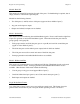
The digital I/O circuitry is designed around an 82C55A integrated circuit. The 82C55A is a
general-purpose PPI containing 24 programmable I/O pins. These pins represent the three 8-bit
I/O ports (A, B, and C) of the 82C55A. These ports can be programmed as two groups of 12
signals or as three individual 8-bit ports. The following paragraphs include programming
information for the Lab-NB along with program examples written in C.
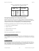
The three 8-bit ports are divided into two groups: group A and group B (two groups of 12
signals). One 8-bit configuration (or control) word specifies the mode of operation for each
group. Group A’s control bits configure port A (A0 through A7) and the upper 4 bits (nibble) of
port C (C4 through C7). Group B’s control bits configure port B (B0 through B7) and the lower
nibble of port C (C0 through C3). These configuration bits are defined later in this chapter.
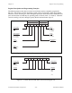
82C55A Modes of Operation
The three basic modes of operation for the 82C55A are as follows:
• Mode 0 – Basic I/O
• Mode 1 – Strobed I/O
• Mode 2 – Bidirectional bus
The 82C55A also has a single bit set/reset feature for port C. The 8-bit control word also
programs this function. For additional information, refer to Appendix D, OKI 82C55A Data
Sheet.