
User's Manual

Chapter 4 Register-Level Programming
© National Instruments Corporation 4-57 Lab-NB User Manual
Register Descriptions and Programming Examples
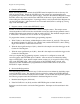
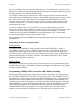
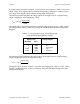
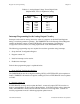
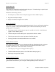
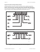
The following figures show the two control-word formats used to completely program the
82C55A. The control-word flag determines which control-word format is being programmed.
When the control-word flag is 1, bits 0 through 6 specify the I/O characteristics of the 82C55A’s
ports and the mode in which they are operating (that is, mode 0, mode 1, or mode 2). When the
control-word flag is 0, bits 3 through 0 specify the bit set/reset format of port C.
D7 D6 D5 D4 D3 D2 D1 D0
Control-Word
Flag
1 = mode set
Mode Selection
00 = mode 0
01 = mode 1
1X = mode 2
Port A
1 = input
0 = output
Port C
(low nibble)
1 = input
0 = output
Port B
1 = input
0 = output
Mode Selection
0 = mode 0
1 = mode 1
Group A Group B
Port C
(high nibble)
1 = input
0 = output
Figure 4-1. Control-Word Format with Control-Word Flag Set to 1
D7 D3 D2 D1 D0
Control-Word
Flag
0 = Bit
Set/Reset
Unused
Bit Set/Reset
1 = set
0 = reset
Bit Select
(000)
(001)
(010)
:
:
(111)
XXX
Figure 4-2. Control-Word Format with Control-Word Flag Set to 0