
User's Manual

Chapter 4 Register-Level Programming
© National Instruments Corporation 4-63 Lab-NB User Manual
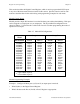
Mode 1 Output Programming Example
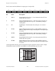
Example 1. Configure port A as an output port in mode 1:
• Write A0 (hex) to the Digital Control Register.
• Wait for bit 7 of port C (OBFA*) to be cleared, indicating that the data last written to port A
has been read.
• Write new data to port A.
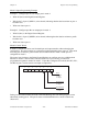
Example 2. Configure port B as an output port in mode 1:
• Write 84 (hex) to the Digital Control Register.
• Wait for bit 1 of port C (OBFB*) to be cleared, indicating that the data last written to port B
has been read.
• Write new data to port A.
Mode 2 Control Words
In mode 2, an 8-bit bus can be used for both input and output transfers without changing the
configuration. The data transfers are synchronized with handshaking lines in port C. This mode
uses only port A; however, port B can be used in either mode 0 or mode 1 while port A is
configured for mode 2.
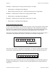
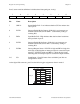
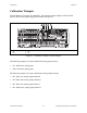
The control word written to the Digital Control Register to configure port A as a bidirectional
data bus in mode 2 is shown below. Because mode 2 is for port A only, port B can be
programmed to operate in mode 0 or mode 1. If port B is configured for mode 0, then PC2, PC1,
and PC0 of port C can be used as extra input or output lines.
Port C
(PC2-PC0)
1 = input
0 = output
Port B direction
1 = input
0 = output
Group B Mode
0 = mode 0
1 = mode 1
1 X X 1/01 1/0X 1/0
765
43210
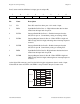
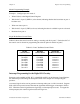
During a mode 2 data transfer, the status of the handshaking lines and interrupt signals can be
obtained by reading port C. The port C status-word bit definitions for a mode 2 transfer are
shown next.