
User's Manual

Configuration and Installation Chapter 2
Lab-NB User Manual 2-8 © National Instruments Corporation
cause conversions to occur; it cannot be used as a monitor to detect conversions caused by the
onboard sample-interval timer.
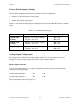
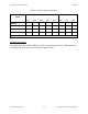
The following input ranges and maximum ratings apply to inputs ACH<0..7>:
Input impedance 0.1 GΩ in parallel with 45 pF
Input signal range Bipolar input: ±(5 / gain) V
Unipolar input: 0 to (10 / gain) V
Maximum input voltage rating ±45 V powered on or off
Exceeding the input signal range for gain settings greater than 1 will not damage the input
circuitry as long as the maximum input voltage rating of ±45 V is not exceeded. For example,
with a gain of 10, the input signal range is ±0.5 V for bipolar input and 0 to 1 V for unipolar
input, but the Lab-NB is guaranteed to withstand inputs up to the maximum input voltage rating.
Warning: Exceeding the input signal range will result in distorted input signals. Exceeding
the maximum input voltage rating may result in damage to the Lab-NB board and
to the Macintosh computer. National Instruments is
NOT liable for any damages
resulting from any such signal connections.
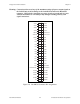
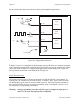
Connections for Signal Sources
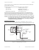
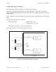
Figure 2-7 shows how to connect a signal source to a Lab-NB board. When you connect
grounded signal sources, observe the polarity carefully to avoid shorting the signal source output.
Signal
Source
I/O Connector
Input Multiplexer
Programmable Gain
Amplifier
Lab-NB Board
AIGND
ACH<0..7>
1
2
3
8
9
V
S3
V
S2
V
S1
+
+
+++
-
-
R
f
R
a
Measured
Voltage
V
M
---
•
•
•
Figure 2-7. Analog Input Signal Connections