
User's Manual

Chapter 2 Configuration and Installation
© National Instruments Corporation 2-9 Lab-NB User Manual
Analog Output Signal Connections
Pins 10 through 12 of the I/O connector are analog output signal pins.
Pins 10 and 12 are the DAC0 OUT and DAC1 OUT signal pins. DAC0 OUT is the voltage
output signal for Analog Output Channel 0. DAC1 OUT is the voltage output signal for Analog
Output Channel 1.
Pin 11, AOGND, is the ground reference point for both analog output channels as well as analog
input.
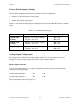
The following output ranges are available:
Output signal range Bipolar input: ±5 V
*
Unipolar input: 0 to 10 V
*
*
Maximum load current = ±1 mA for 12-bit linearity
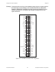
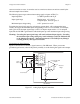
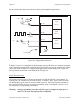
Figure 2-8 shows how to make analog output connections.
Analog Output Channels
VOUT 0
VOUT 1
Load
Load
+
-
AOGND
DAC1 OUT
Channel 1
Channel 0
DAC0 OUT10
11
12
Lab-NB Board
+
-
Figure 2-8. Analog Output Signal Connections