
User's Manual
Configuration and Installation Chapter 2
Lab-NB User Manual 2-10 © National Instruments Corporation
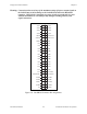
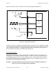
Digital I/O Signal Connections
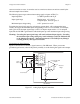
Pins 13 through 37 of the I/O connector are digital I/O signal pins. Digital I/O on the Lab-NB is
designed around the 82C55A integrated circuit. The 82C55A is a general-purpose PPI
containing 24 programmable I/O pins. These pins represent the three 8-bit ports (PA, PB, and
PC) of the 82C55A.
Pins 14 through 21 are connected to the digital lines PA<0..7> for digital I/O port A. Pins 22
through 29 are connected to the digital lines PB<0..7> for digital I/O port B. Pins 30 through 37
are connected to the digital lines PC<0..7> for digital I/O port C. Pin 13, DGND, is the digital
ground pin for all three digital I/O ports.
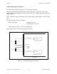
The following specifications and ratings apply to the digital I/O lines.
Absolute maximum voltage input rating +5.5 V with respect to DGND
-0.5 V with respect to DGND
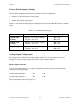
Digital input specifications (referenced to DGND):
V
IH
input logic high voltage 2.2 V min
V
IL
input logic low voltage 0.8 V max
I
IH
input current load,
logic high input voltage 1.0 µA max
I
IL
input current load,
logic low input voltage -1.0 µA max
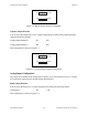
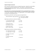
Digital output specifications (referenced to DGND):
V
OH
output logic high voltage 3.7 V min
V
OL
output logic low voltage 0.4 V max
I
OH
output source current,
logic high -2.5 mA max
I
OL
output sink current,
logic low 2.5 mA max