USER GUIDE AND SPECIFICATIONS NI USB-9215 Series 4-Channel, ±10 VDC, 16-Bit Simultaneous Sampling Analog Input Devices This user guide describes how to use the National Instruments USB-9215 Series and lists the specifications. In this document, the NI USB-9215/9215A with screw terminal or backshell and NI USB-9215A with BNC are referred to inclusively as the NI USB-9215 Series.
Dimensions Figures 2 and 3 show the NI USB-9215 Series device dimensions. Hi-Speed USB Carrier NI USB-9162 140.23 mm (5.521 in.) 120.68 mm (4.751 in.) 137.82 mm (5.426 in.) 118.26 mm (4.656 in.) 88.12 mm (3.469 in.) 25.34 mm (0.998 in.) Figure 2. NI USB-9215 (Screw Terminal) in Millimeters (Inches) Hi-Speed USB Carrier NI USB-9162 140.66 mm (5.538 in.) 120.68 mm (4.751 in.) 138.30 mm (5.445 in.) 118.26 mm (4.656 in.) 88.12 mm (3.469 in.) 25.34 mm (0.998 in.) Figure 3.
Safety Guidelines Operate the NI USB-9215 Series only as described in these operating instructions. Although the NI 9215 module may have more stringent certification standards than the NI USB-9215 Series, when used with the NI USB-9161/9162 carrier, the combined system may be limited. Refer to the Specifications section of this document for more details. Note Hot Surface This icon denotes that the component may be hot. Touching this component may result in bodily injury.
Related Documentation Each application software package and driver includes information about writing applications for taking measurements and controlling measurement devices. The following references to documents assume you have NI-DAQmx 8.7 or later, NI-DAQmx Base version 3.x, and where applicable, version 7.1 or later of the NI application software.
Use the LabVIEW Help, available by selecting Help»Search the LabVIEW Help in LabVIEW, to access information about LabVIEW programming concepts, step-by-step instructions for using LabVIEW, and reference information about LabVIEW VIs, functions, palettes, menus, and tools.
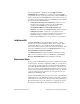
this help file in Visual Studio. NET, select Measurement Studio» NI Measurement Studio Help. To create an application in Visual C++, Visual C#, or Visual Basic .NET, follow these general steps: 1. In Visual Studio .NET, select File»New»Project to launch the New Project dialog box. 2. Find the Measurement Studio folder for the language you want to create a program in. 3. Choose a project type. You add DAQ tasks as a part of this step.
Device Documentation and Specifications NI-DAQmx includes the Device Document Browser, which contains online documentation for supported DAQ and SCXI devices, such as documents describing device pinouts, features, and operation. You can find, view, and/or print the documents for each device using the Device Document Browser at any time by inserting the CD.
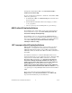
Training Courses If you need more help getting started developing an application with NI products, NI offers training courses. To enroll in a course or obtain a detailed course outline, refer to ni.com/training. Technical Support on the Web For additional support, refer to ni.com/support or zone.ni.com. Installing the Software Software support for the NI USB-9215 Series for Windows Vista/XP/2000 is provided by NI-DAQmx or NI-DAQmx Base depending on the software you are using.
device, and is also accessible from Start»All Programs»National Instruments»NI-DAQ, for more information. The NI-DAQmx Base software ships with example programs you can use to get started programming with the NI USB-9215 Series. Refer to the NI-DAQmx Base Getting Started Guide that shipped with your device, and is also accessible from Start»All Programs»National Instruments» NI-DAQmx Base»Documentation, for more information.
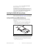
Figure 5. Locking Module into Place Mounting the NI USB-9215 Series to a Panel Thread inserts are located in the NI USB-9215 Series for mounting it to a panel. Refer to Figure 6 for dimensions. 85.7 mm (3.37 in.) 72.2 mm (2.84 in.) Threaded Insert M3 x 0.5 8.5 mm (0.34 in.) Max Depth 76.1 mm (3.00 in.) Figure 6.
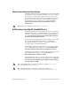
LED Indicator The NI USB-9215 Series device has a green LED next to the USB connector. The LED indicator indicates device status, as listed in Table 2. When the device is connected to a USB port, the LED blinks steadily to indicate that the device is initialized and is receiving power from the connection. If the LED is not blinking, it may mean that the device is not initialized or the computer is in standby mode.
Each channel of the NI USB-9215 Series has a terminal or center pin to which you can connect the positive voltage signal, AI+, and a terminal or shield to which you can connect the negative voltage signal, AI–. The NI USB-9215 with screw terminal also has a common terminal, COM, that is internally connected to the isolated ground reference of the module. Refer to Table 3 for the terminal assignments of the NI USB-9215 with screw terminal.
AI0+ AI0– AI1+ AI1– AI2+ AI2– AI3+ AI3– Figure 7. BNC Connector Assignments Connecting Differential Voltage Signals to the NI USB-9215 Series For grounded differential signals, connect the positive voltage signal to AI+ and the negative signal to AI–. For the NI USB-9215 with screw terminal, connect the signal reference to the COM terminal. AI+ Voltage Source + – AI– NI USB-9215 with Screw Terminal COM Figure 8.
BNC has internal circuitry that keeps the voltage source within the common-mode range. AI+ Voltage Source + – AI– NI USB-9215 with Screw Terminal Resistor COM Figure 9. Connecting a Floating Differential Voltage Signal (NI USB-9215 with Screw Terminal Shown) Connecting Single-Ended Voltage Signals to the NI USB-9215 Series Connect the positive voltage signal to AI+. Connect the ground signal to AI–.
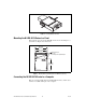
Assembling the High Voltage Screw Terminal Backshell The high voltage screw terminal backshell must be installed when using hazardous voltages (>42.4 Vpk, 60 VDC). Refer to Figure 11 while completing the following steps to assemble the backshell: 1. Connect the leads to the screw terminal and secure with the strain relief. 2. Finish by snapping the backshell around the connector. 1 1 Strain Relief Figure 11. High Voltage Screw Terminal Backshell Figure 12.
NI USB-9215 Series Circuitry The NI USB-9215 Series channels share a common ground. The NI USB-9215 protects each channel from overvoltages. For more information about overvoltage protection, refer to the Specifications section. The signal is buffered and conditioned by the instrumentation amplifier and is then sampled by a 16-bit ADC. The channels have independent track-and-hold amplifiers that allow you to sample all four channels simultaneously.
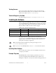
Specifications The following specifications are typical for the range 0 to 60 °C unless otherwise noted. All voltages are relative to COM unless otherwise noted. Input Characteristics Number of channels ............................... 4 analog input channels ADC resolution ...................................... 16 bits Type of ADC..........................................
Conversion time Channel 0 only.................................4.4 μs Channels 0 and 1 .............................6 μs Channels 0, 1, and 2 ........................8 μs Channels 0, 1, 2, and 3 ....................10 μs Accuracy Percent of Reading (Gain Error) Percent of Range (Offset Error)* Calibrated max (0 to 60 °C) 0.2% 0.082% Calibrated typ (25 °C, ±5 °C) 0.02% 0.014% Uncalibrated max (0 to 60 °C) 1.05% 0.82% Uncalibrated typ (25 °C, ±5 °C) 0.6% 0.38% Error * Range equals 10.4 V.
Settling time (to 2 LSBs) With screw terminal 10 V step .................................. 10 μs 20 V step .................................. 15 μs With BNC 10 V step .................................. 25 μs 20 V step .................................. 35 μs No missing codes ................................... 15 bits guaranteed DNL ....................................................... –1.9 to 2 LSB max INL .........................................................
Safety If you need to clean the module, wipe it with a dry towel. Safety Voltages NI USB-9215 with Screw Terminal Safety Voltages Connect only voltages that are within these limits. Channel-to-COM ....................................±30 V max Isolation Channel-to-channel..........................No isolation between channels Channel-to-earth ground Withstand .................................2,300 Vrms, 5 seconds max Continuous ...............................
Safety Standards This product is designed to meet the requirements of the following standards of safety for electrical equipment for measurement, control, and laboratory use: Note • IEC 61010-1, EN-61010-1 • UL 61010-1, CSA 61010-1 For UL and other safety certifications, refer to the product label or visit ni.com/certification, search by model number or product line, and click the appropriate link in the Certification column.
CE Compliance This product meets the essential requirements of applicable European Directives, as amended for CE marking, as follows: • 2006/95/EC; Low-Voltage Directive (safety) • 2004/108/EC; Electromagnetic Compatibility Directive (EMC) Refer to the Declaration of Conformity (DoC) for this product for any additional regulatory compliance information. To obtain the DoC for this product, visit ni.
Where to Go for Support The National Instruments Web site is your complete resource for technical support. At ni.com/support you have access to everything from troubleshooting and application development self-help resources to email and phone assistance from NI Application Engineers. National Instruments corporate headquarters is located at 11500 North Mopac Expressway, Austin, Texas, 78759-3504. National Instruments also has offices located around the world to help address your support needs.