DAQ 6527 User Manual Isolated Digital I/O Interface for PCI, PXI ™, and CompactPCI 6527 User Manual August 2000 Edition Part Number 322164B-01
Worldwide Technical Support and Product Information ni.
Important Information Warranty The PCI-6527 and PXI-6527 devices are warranted against defects in materials and workmanship for a period of one year from the date of shipment, as evidenced by receipts or other documentation. National Instruments will, at its option, repair or replace equipment that proves to be defective during the warranty period. This warranty includes parts and labor.
Contents About This Manual How To Use the Manual Set..........................................................................................vii Conventions ...................................................................................................................viii Related Documentation..................................................................................................viii Chapter 1 Getting Started with Your 6527 About the 6527 Device ..............................................
Contents Output Channels.............................................................................................. 3-10 Overcurrent Protection .................................................................................... 3-12 Power-on and Power-off Conditions............................................................... 3-13 Chapter 4 Using the 6527 Functional Overview .....................................................................................................
About This Manual This manual describes the electrical and mechanical aspects of the 6527 devices, and contains information concerning their operation and programming. How To Use the Manual Set The 6527 User Manual is one piece of the documentation set for your data acquisition system. You could have any of several types of manuals, depending on the hardware and software in your system.
About This Manual Conventions The following conventions appear in this manual: <> Angle brackets that contain numbers separated by an ellipsis represent a range of values associated with a bit or signal name—for example, DIG+0.<3..0>. ♦ The ♦ symbol indicates that the text following it applies only to a specific product, a specific operating system, or a specific software version. This icon denotes a note, which alerts you to important information.
Getting Started with Your 6527 1 This chapter describes the 6527 devices, lists what you need to get started, software programming choices, and optional equipment, describes custom cabling options, and explains how to unpack your board. About the 6527 Device Thank you for purchasing a National Instruments 6527 device. Unless otherwise noted, the text applies to all devices in the 6527 family, which includes the PCI-6527 and PXI-6527.
Chapter 1 Getting Started with Your 6527 Using PXI with CompactPCI Using PXI-compatible products with standard CompactPCI products is an important feature provided by the PXI Specification, Revision 1.0. If you use a PXI-compatible plug-in device in a standard CompactPCI chassis, you will be unable to use PXI-specific functions, but you can still use the basic plug-in device functions.
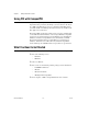
Chapter 1 Getting Started with Your 6527 Software Programming Choices There are several options to choose from when programming your National Instruments DAQ hardware. You can use LabVIEW, LabWindows/CVI, Visual C++, or Visual Basic with the NI-DAQ driver software. National Instruments Application Software LabVIEW features interactive graphics, a state-of-the-art user interface, and a powerful graphical programming language.
Chapter 1 Getting Started with Your 6527 LabVIEW or Measurement Studio Conventional Programming Environment NI-DAQ Driver Software DAQ or SCXI Hardware Personal Computer or Workstation Figure 1-1.
Chapter 1 Getting Started with Your 6527 Custom Cabling National Instruments offers cables and accessories for you to prototype your application or to use if you frequently change board interconnections. If you want to develop your own cable, note that the 6527 device uses a 100-pin female cable header. AMP Corporation part number 749621-9 may be used for the mating connector.
Chapter 1 Getting Started with Your 6527 Unpacking Your 6527 device is shipped in an antistatic package to prevent electrostatic damage to the board. Electrostatic discharge can damage several components on the board. To avoid such damage in handling the board, take the following precautions: • Ground yourself via a grounding strap or by holding a grounded object. • Touch the antistatic package to a metal part of your computer chassis before removing the board from the package.
Installing and Configuring the 6527 2 This chapter describes how to install and configure your 6527 device. Installing Software This section describes how to install your software. Note Install your software before you install your 6527 device. If you are using NI-DAQ, refer to your NI-DAQ release notes for specific instructions on the software installation sequence. Find the installation section for your operating system and follow the instructions given there.
Chapter 2 Installing and Configuring the 6527 ♦ PCI-6527 To install a PCI-6527 in any available 5 V PCI expansion slot in your computer: 1. Turn off and unplug your computer. 2. Remove the top cover or access port to the expansion slots. 3. Make sure there are no lighted LEDs on your motherboard. If any are lit, wait until they go out before continuing your installation. 4. Remove the expansion slot cover on the back panel of the computer. 5.
Chapter 2 Installing and Configuring the 6527 Your 6527 is now installed. You are now ready to configure your hardware and software. Configuring the 6527 Your 6527 device is completely software configurable, and you do not need to perform any configuration steps after the system powers up. The PCI-6527 is fully compliant with the PCI Local Bus Specification, Revision 2.0, and the PXI-6527 is fully compliant with the PXI Specification, Revision 1.0.
Making Signal Connections 3 This chapter describes the pin arrangement, signal names, and signal connections on your 6527 device. Connections that exceed any of the maximum ratings of input or output signals on your 6527 device can damage the board and your computer. Pay careful attention to the maximum input ratings included with the description of each signal in this chapter. National Instruments is not liable for any damages resulting from signal connections that exceed these maximum ratings.
Chapter 3 Making Signal Connections For input ports, connect the higher voltage to the DIG+ pin and the lower voltage to the DIG– pin. For output ports, you can connect signals to the two pins of each line without regard to which voltage is higher. The output lines consist of solid-state relays and act as bidirectional switches. Note Input DIG+2.7 DIG–2.7 DIG+2.6 DIG–2.6 DIG+2.5 DIG–2.5 DIG+2.4 DIG–2.4 DIG+2.3 DIG–2.3 DIG+2.2 DIG–2.2 DIG+2.1 DIG–2.1 DIG+2.0 DIG–2.0 DIG+1.7 DIG–1.7 DIG+1.6 DIG–1.
Chapter 3 Making Signal Connections Table 3-1. Port Functionality for 6527 Devices Port Function 0 Input 1 Input 2 Input 3 Output with readback 4 Output with readback 5 Output with readback Cable Assembly Connectors The optional R1005050 cable assembly you can use with the 6527 device is an assembly of two 50-pin cables and three connectors. Both cables are joined to a single connector on one end and to individual connectors on the free ends.
Chapter 3 Making Signal Connections Input DIG+2.7 DIG+2.6 DIG+2.5 DIG+2.4 DIG+2.3 DIG+2.2 DIG+2.1 DIG+2.0 DIG+1.7 DIG+1.6 DIG+1.5 DIG+1.4 DIG+1.3 DIG+1.2 DIG+1.1 DIG+1.0 DIG+0.7 DIG+0.6 DIG+0.5 DIG+0.4 DIG+0.3 DIG+0.2 DIG+0.1 DIG+0.0 +5 V 1 3 5 7 9 11 13 15 17 19 21 23 25 27 29 31 33 35 37 39 41 43 45 47 49 2 4 6 8 10 12 14 16 18 20 22 24 26 28 30 32 34 36 38 40 42 44 46 48 50 Output with Readback DIG–2.7 DIG+5.7 DIG–2.6 DIG+5.6 DIG–2.5 DIG+5.5 DIG–2.4 DIG+5.4 DIG–2.3 DIG+5.3 DIG–2.2 DIG+5.
Chapter 3 Making Signal Connections I/O Connector Signal Descriptions Table 3-2. Signal Descriptions for 6527 I/O Connector Pins Pin Signal Name 33, 35, 37, 39, 41, 43, 45, 47 DIG+0.<7..0> Isolated input port 0, positive terminals—Take measurements at these terminals. These terminals should be positive relative to their corresponding DIG– lines. A logic high (data bit of 1) indicates input voltage and current are present. 34, 36, 38, 40, 42, 44, 46, 48 DIG–0.<7..
Chapter 3 Making Signal Connections Table 3-2. Signal Descriptions for 6527 I/O Connector Pins (Continued) Pin Signal Name Description 83, 85, 87, 89, 91, 93, 95, 97 DIG+3.<7..0> Isolated output port 3, first terminals—Each of these is the first of two terminals of a bidirectional solid-state relay1. A logic low (data bit of 0) closes the relay. 84, 86, 88, 90, 92, 94, 96, 98 DIG–3.<7..
Chapter 3 Making Signal Connections Isolation Voltages The positive and negative (DIG+ and DIG–) terminals of each channel are isolated from the other input and output channels, from the +5 V and GND pins, and from the computer power supply. Isolation barriers provide isolation up to 60 VDC or 30 VAC (42 V peak) between any two terminals, except between the two terminals making up a single digital I/O channel.
Chapter 3 Making Signal Connections Sensing DC Voltages When you apply a DC voltage of at least 2 V across the two input terminals, the 6527 device registers a logic high for that input. If no voltage is present (a voltage difference of 1 V or less), the 6527 device registers a logic low for that input. DC voltages between 1 V and 2 V are invalid and register an unreliable value.
Chapter 3 Making Signal Connections Reducing the Forward Current for High Voltages As input voltage increases above 5 V, the input current drawn by the 6527 (forward current If) also rises. At 24 V, for example, current per line is found by the following equation: ( 24V – 1.5V ) -------------------------------- = 7.
Chapter 3 Making Signal Connections Solid-State Relay Outputs On a 6527 device, I/O connector pins 51 through 98, shown in Figure 3-1, represent the terminals of the solid-state relays. Output Channels The output channels of a 6527 device are solid-state relays containing an LED and two MOSFETs connected together to form a bidirectional switch. The LH1546 is a solid-state relay. Depending on how the load is connected to the terminals, an output can either source or sink currents.
Chapter 3 Making Signal Connections Writing a 0 (logic low) to an output bit closes the relay, and writing a 1 (logic high) opens the relay. To both sink and source current with one channel requires an external resistor. You can use the solid-state relays of a 6527 device with external resistors to drive voltages at TTL or non-TTL levels, from –60 to 60 VDC or 30 VAC (42 V peak).
Chapter 3 Making Signal Connections The following equation shows the minimum sink current when VOUT is 0.5 V: 0.5V ( 5V – 0.5V ) ----------- – ----------------------------- = 13.4 mA 35 Ω 5 kΩ 6527 +5 V To External +5 V Supply RL= 5 k 390 VOUT 35 If Digital Logic Isolation Isolated Ground Figure 3-6.
Chapter 3 Making Signal Connections The overcurrent protection ratings for a 6527 device are as follows (typical at 25 °C): • Overcurrent protection limit = 260 mA • Current limit time = 1 µs at 7 V • Duration of current above operating current (120 mA): 1 s max at 7 V Overcurrent protection is for protection against transient fault conditions only. The 6527 should not normally be operated above 120 mA.
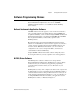
4 Using the 6527 This chapter contains a functional overview of the 6527 device, explains the operation of each functional unit, and describes the digital filter and change detection options. Functional Overview The block diagram in Figure 4-1 illustrates the key functional components of your 6527 device, which includes PCI interface circuitry, digital I/O circuitry, and optical isolation circuitry.
Using the 6527 Port 0 Isolation Port 1 Isolation PCI or PXI Bus PCI MITE Interface Digital I/O Circuitry (FPGA) Port 2 Isolation EEPROM Port 3 Isolation Port 4 Isolation EEPROM Port 5 Isolation Port 0 16 Port 1 16 Port 2 16 Port 3 I/O Connector Chapter 4 16 Port 4 16 Port 5 16 Figure 4-1. 6527 Block Diagram PCI Interface Circuitry Your 6527 board uses the PCI MITE ASIC, designed by National Instruments specifically for data acquisition, to communicate with the PCI bus.
Chapter 4 Using the 6527 Digital I/O Circuitry You can use your 6527 board as follows: • • Output ports – Write – Read back Input ports – Read – Apply digital filtering (software programmable) – Change detection on selected lines (software programmable) Table 3-1, Port Functionality for 6527 Devices, contains a summary of port functions. Optical Isolation Circuitry The 5211 optocouplers optically isolate the digital input ports of a 6527 device.
Chapter 4 Using the 6527 The filter operates on the inputs from the optocouplers. The optocouplers turn on faster than they turn off, passing rising edges faster than falling edges. The optocouplers can therefore add up to 100 µs to a high pulse or subtract up to 100 µs from a low pulse (a 100 µs change is typical at If = 5 mA, RL = 100 Ω). As a result, the pulse widths guaranteed to be passed and blocked are those shown in Table 4-1. Table 4-1.
Chapter 4 Using the 6527 External Signal Filter Clock Sample Clock (100 ns) External Signal Sampled H H L L H H L L B H H H H H H H C A Filtered Signal Figure 4-2. Digital Filter Timing Change Notification You can program the 6527 to notify you of changes on input lines. Change notification can reduce the number of reads your software must perform to monitor inputs. Instead of reading the inputs continuously, your software reacts only to transitions.
Chapter 4 Using the 6527 • Bit 1 is connected to a limit sensor; the 6527 detects rising edges on the sensor, which correspond to over-limit conditions. • Bit 0 is connected to a switch. Your software can react to any switch closure, represented by a falling edge. If the switch closure is noisy, you should also enable digital filtering for at least this line. In this example, the 6527 reports rising edges only on bit 1, falling edges only on bit 0, and rising and falling edges on bits 7, 6, 5, and 4.
A Specifications This appendix lists the specifications for the 6527 devices. These specifications are typical at 25 °C unless otherwise noted. Digital I/O PCI/PXI-6527......................................... 24 optically-isolated digital input channels and 24 solid-state relay output channels Isolated Inputs Number of input channels ...................... 24, each with its own ground reference isolated from other channels Max input voltage ..................................
Appendix A Specifications Max switching voltage AC....................................................30 VRMS (42 V peak) DC....................................................60 VDC Max switching capacity ..........................120 mA1 Common-mode isolation ........................60 VDC 30 VRMS (42 V peak) (channel-to-channel and channel-to-computer) On resistance...........................................35 Ω max; 25 Ω typ Output capacitance .................................
Appendix A Specifications Physical Dimensions (not including connectors) PCI-6527 ......................................... 17.5 × 10.7 cm (6.9 × 4.2 in.) PXI-6527......................................... 16 × 10 cm (6.3 × 3.9 in.) I/O connector.......................................... 100-pin keyed female cable connector Environment Operating temperature............................ 0 to 50 °C Storage temperature ............................... –20 to 70 °C Relative humidity ............................
Technical Support Resources B Web Support National Instruments Web support is your first stop for help in solving installation, configuration, and application problems and questions. Online problem-solving and diagnostic resources include frequently asked questions, knowledge bases, product-specific troubleshooting wizards, manuals, drivers, software updates, and more. Web support is available through the Technical Support section of ni.com NI Developer Zone The NI Developer Zone at ni.
Appendix B Technical Support Resources Worldwide Support National Instruments has offices located around the world to help address your support needs. You can access our branch office Web sites from the Worldwide Offices section of ni.com. Branch office Web sites provide up-to-date contact information, support phone numbers, e-mail addresses, and current events.
Glossary Prefix Meanings Value n- nano- 10 –9 µ- micro- 10 – 6 m- milli- 10 –3 k- kilo- 10 3 Numbers/Symbols ° degrees – negative of, or minus Ω ohms / per % percent ± plus or minus + positive of, or plus +5 V +5 Volts signal A A amperes AC alternating current ANSI American National Standards Institute ASIC Application-Specific Integrated Circuit—a proprietary semiconductor component designed and manufactured to perform a set of specific functions © National Instrument
Glossary C C Celsius CAT I installation category (overvoltage category) I—equipment for which measures are taken to limit transient overvoltages to an appropriate low level. Examples include signal-level, telecommunications, and electronic equipment with transient overvoltages smaller than local-level mains supplies.
Glossary I I/O input/output in.
Glossary S s seconds T TTL transistor-transistor logic, or 5 V digital voltage levels originally used with transistor-transistor logic V V volts Vcc supply voltage; for example, the voltage a computer supplies to its plug-in devices VDC volts direct current VI virtual instrument—a combination of hardware and/or software elements, typically used with a PC, that has the functionality of a classic standalone instrument VIN input voltage W W 6527 User Manual watts G-4 ni.
Index Numbers CompactPCI, using with PXI, 1-2 configuration, 2-3 connector. See I/O connector.
Index E L environment specifications, A-3 equipment, optional, 1-4 LabVIEW software, 1-3 LabWindows/CVI software, 1-3 F M filtering. See digital filtering. forward current for high voltages, reducing, 3-9 fuse, self-resetting, 3-6 manual. See documentation.
Index power-on and power-off conditions, 3-13 software installation, 2-1 software programming choices, 1-3 to 1-4 National Instruments application software, 1-3 NI-DAQ driver software, 1-3 to 1-4 solid-state relay outputs, 3-10 to 3-13 output channels, 3-10 to 3-12 driving a load (example), 3-10 to 3-11 maximum power ratings, 3-12 sinking and sourcing current (example), 3-11 to 3-12 overcurrent protection, 3-12 to 3-13 power-on and power-off conditions, 3-13 specifications, A-1 to A-2 specifications, A-1 t