™ DAQCard -700 User Manual Multifunction I/O Board for the PCMCIA Bus January 1996 Edition Part Number 320676C-01 © Copyright 1994, 1996 National Instruments Corporation. All Rights Reserved.
National Instruments Corporate Headquarters 6504 Bridge Point Parkway Austin, TX 78730-5039 (512) 794-0100 Technical support fax: (800) 328-2203 (512) 794-5678 Branch Offices: Australia 03 9 879 9422, Austria 0662 45 79 90 0, Belgium 02 757 00 20, Canada (Ontario) 519 622 9310, Canada (Québec) 514 694 8521, Denmark 45 76 26 00, Finland 90 527 2321, France 1 48 14 24 24, Germany 089 741 31 30, Hong Kong 2645 3186, Italy 02 48301892, Japan 03 5472 2970, Korea 02 596 7456, Mexico 95 800 010 0793, Netherlands 0
Limited Warranty The DAQCard-700 is warranted against defects in materials and workmanship for a period of one year from the date of shipment, as evidenced by receipts or other documentation. National Instruments will, at its option, repair or replace equipment that proves to be defective during the warranty period. This warranty includes parts and labor.
WARNING REGARDING MEDICAL AND CLINICAL USE OF NATIONAL INSTRUMENTS PRODUCTS National Instruments products are not designed with components and testing intended to ensure a level of reliability suitable for use in treatment and diagnosis of humans. Applications of National Instruments products involving medical or clinical treatment can create a potential for accidental injury caused by product failure, or by errors on the part of the user or application designer.
Contents ___________________________________________________ About This Manual .............................................................................................................ix Organization of This Manual .........................................................................................ix Conventions Used in This Manual .................................................................................x National Instruments Documentation ...................................................
Contents Differential Connection Considerations (DIFF Configuration) .............3-8 Differential Connections for Grounded Signal Sources ............3-9 Differential Connections for Floating Signal Sources ...............3-10 Common-Mode Signal Rejection Considerations......................3-11 Digital I/O Signal Connections ..........................................................................3-12 Power Connections .....................................................................................
Contents Figures Figure 1-1. The Relationship between the Programming Environment, NI-DAQ, and Your Hardware..............................................................................................1-3 Figure 2-1. A Typical Configuration for the DAQCard-700 ................................................2-2 Figure 3-1. Figure 3-2. Figure 3-3. Figure 3-4. Figure 3-5. Figure 3-6. Figure 3-7. Figure 3-8. Figure 3-9. Figure 3-10. DAQCard-700 I/O Connector Pin Assignments..............................
About This Manual This manual describes the mechanical and electrical aspects of the DAQCard-700 and contains information concerning its installation and operation. The DAQCard-700 is a compact, low-cost, low-power analog input, digital, and timing I/O card for computers that are equipped with a Type II PCMCIA socket.
About This Manual Conventions Used in This Manual The following conventions are used in this manual: bold italic Bold italic text denotes a note, caution, or warning. italic Italic text denotes emphasis, a cross reference, or an introduction to a key concept. Macintosh Macintosh refers to all Macintosh II, Macintosh Quadra, and Macintosh Centris computers except the Centris 610 unless otherwise noted.
About This Manual • Software documentation—Examples of software documentation you may have are the LabVIEW and LabWindows/CVI manual sets and the NI-DAQ documentation (a 4.6.1 or earlier version of NI-DAQ supports LabWindows for DOS). After you set up your hardware system, use either the application software (LabVIEW or LabWindows/CVI) manuals or the NI-DAQ documentation to help you write your application.
Chapter 1 Introduction This chapter describes the DAQCard-700; lists what you need to get started, software programming choices, and optional equipment; and explains how to unpack the DAQCard-700. About the DAQCard-700 Thank you for your purchase of the National Instruments DAQCard-700. The DAQCard-700 is a low-cost, low-power analog input, digital, and timing I/O card for computers equipped with a Type II PCMCIA slot.
Introduction Chapter 1 What You Need to Get Started To set up and use your DAQCard-700, you will need the following: DAQCard-700 One of the following I/O cables (must be purchased separately): PR50-50M ribbon cable (6 in.) PR50-50F ribbon cable (0.5, 1, or 2 m) Connector block for signals DAQCard-700 User Manual NI-DAQ software with documentation Your computer Software Programming Choices There are several options to choose from when programming your National Instruments DAQ and SCXI hardware.
Chapter 1 Introduction NI-DAQ Driver Software The NI-DAQ driver software is included at no charge with all National Instruments DAQ hardware. NI-DAQ is not packaged with SCXI or accessory products, except for the SCXI-1200. NI-DAQ has an extensive library of functions that you can call from your application programming environment.
Introduction Chapter 1 Register-Level Programming The final option for programming any National Instruments DAQ hardware is to write registerlevel software. Writing register-level programming software can be very time-consuming and inefficient and is not recommended for most users. Even if you are an experienced register-level programmer, consider using NI-DAQ, LabVIEW, or LabWindows/CVI to program your National Instruments DAQ hardware.
Chapter 2 Installation and Configuration This chapter describes how to install and software configure the DAQCard-700. Installation Your computer should be equipped with Card and Socket Services 2.0 or later. The DAQCard-700 requires a 32-byte I/O address window and one interrupt level. This manual assumes that you are using one of the optional cables from National Instruments. Notice that the cable is keyed so that you can insert it only one way. Insert the DAQCard-700 and attach the I/O cable.
Installation and Configuration Chapter 2 Portable Computer IN S E R T C A R D PCMCIA Socket DA QC ard ™- I/O Cable 70 0 t I/O Signals The IN NA ST TI Sof twa RU ON re AL ® is M the EN Ins tru T menS CB-50 Figure 2-1. A Typical Configuration for the DAQCard-700 The DAQCard-700 is now installed. You are ready to make the appropriate connections to the I/O connector cable as described in Chapter 3, Signal Connections, and to install and configure your software.
Chapter 2 Installation and Configuration If you are using LabWindows/CVI, the software installation instructions are in Part 1, Introduction to LabWindows/CVI, of the Getting Started with LabWindows/CVI manual. After you have installed LabWindows/CVI, refer to Chapter 1, Configuring LabWindows/CVI, of the LabWindows/CVI User Manual for software configuration instructions.
Installation and Configuration Chapter 2 Table 2-2. Analog Input Modes for the DAQCard-700 Analog Input Modes Description RSE Referenced single-ended mode provides 16 single-ended inputs referenced to analog ground (default setting).
Chapter 2 Installation and Configuration Digital I/O Configuration The DAQCard-700 always uses one 8-bit digital output port and one 8-bit digital input port. Counter Configuration You can use the MSM82C54 counter/timers for general-purpose applications, such as pulse and square wave generation, event counting, and pulse-width, time-lapse, and frequency measurement. For information about configuring the MSM82C54, see the Timing Connections section of Chapter 3, Signal Connections.
Chapter 3 Signal Connections This chapter describes the signals on the DAQCard-700 I/O connector, as well as typical cable setups. I/O Connector Figure 3-1 shows the pin assignments for the DAQCard-700 I/O connector. This connector is attached to the ribbon cable that extends from the PCMCIA slot when the card is installed and the cable is connected. Warning: Connections that exceed any of the maximum ratings of input or output signals on the DAQCard-700 can damage the DAQCard-700 card and the computer.
Signal Connections Chapter 3 AIGND 1 2 AIGND ACH0 3 4 ACH8 ACH1 5 6 ACH9 ACH2 7 8 ACH10 ACH3 9 10 ACH11 ACH4 11 12 ACH12 ACH5 13 14 ACH13 ACH6 15 16 ACH14 ACH7 17 18 ACH15 DGND 19 20 NC NC 21 22 DIN0 DIN1 23 24 DIN2 DIN3 25 26 DIN4 DIN5 27 28 DIN6 DIN7 29 30 DOUT0 DOUT1 31 32 DOUT2 DOUT3 33 34 DOUT4 DOUT5 35 36 DOUT6 DOUT7 37 38 OUT1* EXTINT* 39 40 EXTCONV* OUT0 41 42 GATE0 OUT1 43 44 GATE1 CLK1 45 46 OUT2 GATE2 47 48 CLK2 +5 V 49 5
Chapter 3 Signal Connections Signal Connection Descriptions Pin Signal Name Direction Description 1–2 AIGND — Analog Input Ground—These pins are connected to the analog input ground signal. 3–18 ACH<0..15> Input Analog Input Channels 0 through 15—These channels are in single-ended mode. 19 DGND — Digital Ground—This pin is connected to the digital ground signal. 20–21 NC — Not Connected—These pins are not connected. 22–29 DIN<0..
Signal Connections Chapter 3 The connector pins can be grouped into analog input signal pins, digital I/O signal pins, and timing I/O signal pins. Signal connection guidelines for each of these groups are included in the following pages. Analog Input Signal Connections Pins 1 through 18 are analog input signal pins for the ADC. Pins 1 and 2, AIGND, are an analog common signal. You can use these pins for a general analog power ground tie to the DAQCard-700. Pins 3 through 18 are the ACH<15..
Chapter 3 Signal Connections isolation amplifiers. The ground reference of a floating signal must be tied to the DAQCard-700 analog input ground to establish a local or onboard reference for the signal. Otherwise, the measured input signal varies or appears to float. An instrument or device that provides an isolated output falls into the floating signal source category.
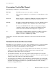
Signal Connections Chapter 3 V in+ + Instrumentation Amplifier + V in- Vm Measured Voltage - - V m= [ V in+ - V in- ] * GAIN Figure 3-2. DAQCard-700 Instrumentation Amplifier The DAQCard-700 instrumentation amplifier applies common-mode voltage rejection and presents a high-input impedance to the analog input signals connected to the DAQCard-700. Signals are routed to the positive and negative inputs of the instrumentation amplifier through input multiplexers on the DAQCard-700.
Chapter 3 Signal Connections Recommended Input Configurations The following sections discuss the use of single-ended and differential measurements and considerations for measuring both floating and ground-referenced signal sources. Table 3-1 summarizes the recommended input configurations for both types of signal sources. Table 3-1.
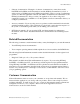
Signal Connections Chapter 3 3 ACH<0..15> 4 5 + Signal Source V S1 + V S2 V S3 - - - Operational Amplifier + + 18 1, 2 + Measured VM Voltage Input Multiplexer - AIGND I/O Connector - DAQCard-700 Figure 3-3. Single-Ended Analog Input Signal Connections Differential Connection Considerations (DIFF Configuration) Differential connections are those in which each DAQCard-700 analog input signal has its own reference signal or signal return path.
Chapter 3 Signal Connections Differential signal connections reduce picked-up noise and increase common-mode signal and noise rejection. With these connections, input signals can float within the common-mode limits of the input instrumentation amplifier. Differential Connections for Grounded Signal Sources Figure 3-4 shows how to connect a ground-referenced signal source to a DAQCard-700 card configured for DIFF input. ACH<0..7> 3 GroundReferenced Signal Source 5 + 7 Vs - + 17 + ACH<8..
Signal Connections Chapter 3 Differential Connections for Floating Signal Sources Figure 3-5 shows how to connect a floating signal source to an DAQCard-700 card configured for DIFF input. Configuration instructions are included in the Input Configurations section earlier in this chapter. 3 ACH<0..7> 5 Floating Signal Source + 100 kΩ V s 7 + 17 - 4 Instrumentation Amplifier + ACH<8..
Chapter 3 Signal Connections the instrumentation amplifier contributes a DC offset voltage at the input. The amplifier has a maximum input offset current of ±0.75 nA and a typical offset current drift of ±1.5 pA/° C. Multiplied by the 100 kΩ resistor, this current contributes a maximum offset voltage of 75 µV and a typical offset voltage drift of 150 nV/° C at the input. Thus, the offset is unlikely to be more than an LSB, so it can usually be ignored.
Signal Connections Chapter 3 Digital I/O Signal Connections Pins 22 through 37 of the I/O connector are digital I/O signal pins. Pins 22 through 29 are digital input pins. Pins 30 through 37 are digital output pins. Pins 19 and 50 are digital ground pins. The following specifications and ratings apply to the digital I/O lines. • Absolute maximum voltage input rating +5.5 V with respect to DGND -0.
Chapter 3 Signal Connections Digital Input Port 22 DIN0 TTL Signal 29 DIN7 +5 V 19 +5 V Digital Output Port LED DGND 30 DOUT0 I/O Connector DAQCard-700 Figure 3-6. Digital I/O Signal Connections Power Connections Pin 49 of the I/O connector sends +5 V from the PCMCIA I/O channel power supply. This pin is referenced to DGND and can be used to power external digital circuitry that draws up to 1 A. Pin 49 is connected to a 1 A resettable fuse on the card.
Signal Connections Chapter 3 Timing Connections Pins 38 through 48 of the I/O connector are connections for timing I/O signals. The DAQCard-700 timing I/O uses an MSM82C54 counter/timer integrated circuit. All three counters of the MSM82C54 are available at the I/O connector. One of these counters, counter 0, is used for data acquisition timing. Pin 40 carries an external signal, EXTCONV*, that can be used for data acquisition timing in place of counter 0 of the MSM82C54.
Chapter 3 Signal Connections programmed for various operations. The only exceptions are counter 0, which has an internal 1 MHz clock, and counter 1, which can also be configured to use this clock. The MSM82C54 counter/timer is described briefly in Chapter 4, Theory of Operation. For more detailed programming information, consult the MSM82C54 Data Sheet in the optional DAQCard-700 Register-Level Programmer Manual.
Signal Connections Chapter 3 To measure time lapse, program a counter to be edge gated. Apply an edge to the counter GATE input to start the counter. Program the counter to start counting after receiving a low-to-high edge. The time lapse since receiving the edge equals the counter value difference (loaded value minus the read value) multiplied by the CLK period. To measure frequency, program a counter to be level gated and count the number of falling edges in a signal applied to a CLK input.
Chapter 3 Signal Connections • Absolute maximum voltage input rating • MSM82C54 digital input specifications (referenced to DGND): • -0.5 to 5.0 V with respect to DGND – VIH input logic high voltage 2.2 V minimum – VIL input logic low voltage 0.8 V maximum – Input load current ±10.0 µA maximum MSM82C54 digital output specifications (referenced to DGND): – VOH output logic high voltage 3.0 V minimum – VOL output logic low voltage 0.40 V maximum – IOH output source current, at VOH 2.
Signal Connections Chapter 3 Cabling National Instruments currently offers two different cables for use with the DAQCard-700, the PR-50-50F and the PR-50-50M. National Instruments also offers a cable termination accessory, the CB-50, for use with the DAQCard-700. This kit includes a terminated, 50-conductor, flat ribbon cable and a connector block. You can attach signal input and output wires to screw terminals on the connector block and therefore, to the DAQCard-700 I/O connector.
Chapter 4 Theory of Operation This chapter includes an overview of the DAQCard-700 and explains the operation of each functional unit making up the DAQCard-700. Functional Overview The block diagram in Figure 4-1 shows a functional overview of the DAQCard-700.
Theory of Operation Chapter 4 The following are the major components making up the DAQCard-700: • PCMCIA I/O channel interface circuitry • Analog input circuitry • Digital I/O circuitry • Timing I/O circuitry Data acquisition functions can be executed by using the analog input circuitry and some of the timing I/O circuitry. The internal data and control buses interconnect the components. The theory of operation for each of these components is explained in the remainder of this chapter.
Chapter 4 Theory of Operation When you first insert the card, the system examines information stored in the DAQCard-700 Card Information Structure. This data is used to configure the card appropriately for the system in which it is used. When the system has assigned the card to a section of memory, it updates the PCMCIA control registers and initializes the card.
Theory of Operation Chapter 4 512-Word 12 12-Bit 16 PCMCIA FIFO, Sampling I/O Sign ADC Channel Data A/D Extension Interface Data Buffer Input Mux2 (4-Channel) - A/D RD Input Mux1 Dual (8-Channel SingleEnded) CONVAVAIL 4 Interrupt Interface 8 Scanning Counter MSM82C54 1 MHz 8 I/O Connector PCMCIA I/O Channel Instrumentation Amplifier + OUT0 A/D Timing EXTCONV* CLK0 Figure 4-3.
Chapter 4 Theory of Operation The A/D FIFO generates a signal that indicates when it contains A/D conversion data. The state of this signal can be read from the Status Register. The output from the ADC is a two's complement number ranging from -2,048 to 2,047. The output from the 12-bit ADC is always sign-extended to 16 bits by the card circuitry so that data values read from the FIFO are 16 bits wide.
Theory of Operation Chapter 4 Data Acquisition Rates The maximum data acquisition rate (number of samples per second) is determined by the conversion period of the ADC plus the acquisition time of its track-and-hold stage. During multichannel scanning, the data acquisition rate is further limited by the settling time of the input multiplexers and operational amplifier.
Chapter 4 Theory of Operation Digital I/O Circuitry The DAQCard-700 has 16 digital I/O lines that are TTL-compatible. Pins DIN<0..7> of the I/O connector are digital input lines, and pins DOUT<0..7> are digital output lines. These lines are monitored or driven by the Digital Input Register or the Digital Output Register, respectively. Reading the Digital Input Register returns the current state of DIN<0..7> lines. Writing the Digital Output Register drives the new value onto DOUT<0..7> lines.
Theory of Operation Chapter 4 Timing I/O Circuitry The DAQCard-700 uses an MSM82C54 counter/timer integrated circuit for data acquisition timing and for general-purpose timing I/O functions. Three counters of the MSM82C54 are available for general use, but one of them can be used internally for data acquisition timing. Figure 4-5 shows a block diagram of both groups of timing I/O circuitry.
Chapter 4 Theory of Operation CLK Counter OUT GATE Figure 4-6. Counter Block Diagram Each counter has a clock input pin, a gate input pin, and an output pin labeled CLK, GATE, and OUT, respectively. The MSM82C54 counters are numbered zero through two, and their GATE, CLK, and OUT pins are labeled GATE N, CLK N, and OUT N, where N is the counter number.
Appendix A Specifications This appendix lists the specifications of the DAQCard-700. These specifications are typical at 25° C unless otherwise noted. The operating temperature range is 0° to 70° C. Analog Input Input Characteristics Number of channels ............................................................... 16 single-ended or 8 differential software selectable Type of ADC .......................................................................... Successive approximation Resolution..................
Specifications Appendix A Dynamic Characteristics Settling time ±0.024% accuracy (±1 LSB) for full-scale step ............................................ 25 µs max at ±10 V, ±5 V 10 µs at ±2.5 V (RSE) System noise........................................................................... 0.5 LSB rms at ±5 V range Stability Recommended warm-up time ................................................ 15 min Onboard calibration reference Level ..................................................................
Appendix A Specifications Power Requirement +5 VDC (±5%) ....................................................................... 100 mA in operational mode 70 mA in power-down mode Note: These power usage figures do not include the power used by external devices that you have connected to the fused supply present on the I/O connector. Physical PC Card type .......................................................................... Type II I/O connector.....................................................
Appendix B Differences between the PC-LPM-16 and the DAQCard-700 This appendix contains a summary of differences between the PC-LPM-16 and the DAQCard-700 that may be relevant to you if you are a current PC-LPM-16 user. For a summary of programming differences, refer to the DAQCard-700 Register-Level Programmer Manual. The DAQCard-700 is compatible with the PC-LPM-16.
Appendix C PC Card Questions and Answers This appendix contains a list of common questions and answers relating to PC Card (PCMCIA) operation. The questions are grouped according to the type of information requested. You may find this information useful if you are having difficulty with the PCMCIA system software configuration. Configuration 1. Do I need to use my PCMCIA configuration utility to configure the National Instruments PC Cards? No.
PC Card Questions and Answers Appendix C 3. Is there a way I can conserve power on my PC Card when it is not in use? Yes. If you are using NI-DAQ for PC compatibles version 4.8.0 or later, a DOS utility called DAQPOWER_EXE will switch all National Instruments PC Cards between normal mode and power-down mode. Power-up and power-down icons are also installed for Windows users to access either of these two power-management modes. Resources 1.
Appendix C PC Card Questions and Answers Keep in mind that utilities such as MSD.EXE will sometimes report that an interrupt is in use when it really is not. For example, if the computer has one serial port, COM1, and one parallel port, LPT1, you know that IRQs 4 and 7 are probably in use. In general, IRQ5 is used for LPT2, but if the computer does not have two parallel ports, IRQ5 should be usable. IRQ3 is used for COM2, but if the computer has only has one serial port, IRQ3 should be usable. 5.
Appendix D Power-Management Modes This appendix describes the power-management modes of the DAQCard-700. • Normal Mode—This is the normal operating mode of the DAQCard-700 in which all the circuits are fully functional. This mode draws about 100 mA from the 5 V supply (about 500 mW). • Power-Down Mode—In this mode, the digital circuitry is powered on and is functional. The analog input circuits are powered down by setting the PWRDOWN bit in the PC Card Configuration and Status Register.
Appendix E Customer Communication ___________________________________________________ For your convenience, this appendix contains forms to help you gather the information necessary to help us solve technical problems you might have as well as a form you can use to comment on the product documentation. Filling out a copy of the Technical Support Form before contacting National Instruments helps us help you better and faster. National Instruments provides comprehensive technical assistance around the world.
Technical Support Form ___________________________________________________ Photocopy this form and update it each time you make changes to your software or hardware, and use the completed copy of this form as a reference for your current configuration. Completing this form accurately before contacting National Instruments for technical support helps our applications engineers answer your questions more efficiently.
DAQCard-700 Hardware and Software Configuration Form ___________________________________________________ Record the settings and revisions of your hardware and software on the line to the right of each item. Complete a new copy of this form each time you revise your software or hardware configuration, and use this form as a reference for your current configuration.
Documentation Comment Form ___________________________________________________ National Instruments encourages you to comment on the documentation supplied with our products. This information helps us provide quality products to meet your needs. Title: DAQCard™-700 User Manual Edition Date: January 1996 Part Number: 320676C-01 Please comment on the completeness, clarity, and organization of the manual. If you find errors in the manual, please record the page numbers and describe the errors.
Glossary ___________________________________________________ ° Ω % A AC ACH A/D ADC AIGND AWG BCD C CE CLK CMOS CMRR D/A DAQ DC DGND DIFF DIN DMA DNL DOUT EISA ESP EXTCONV EXTINT F FIFO GATE Prefix Meaning Value pnµmkMG- piconanomicromillikilomegagiga- 10-12 10-9 10-6 10-3 103 106 1012 degrees ohms percent amperes alternating current analog input channel signal analog-to-digital A/D converter analog input ground signal American Wire Gauge binary-coded decimal Celsius card enable signal clock input s
Glossary hex Hz in.
Index A B ACH<0..
Index block diagram, 4-1 compared with PC-LPM-16, B-1 features, 1-1 major components, 4-1 software programming choices LabVIEW and LabWindows/CVI application software, 1-2 NI-DAQ driver software, 1-3 register-level programming, 1-4 unpacking, 1-4 what you need to get started, 1-2 data acquisition counter and timing connections, 3-14 data acquisition timing circuitry block diagram, 4-4 data acquisition rates, 4-6 multichannel (scanned) data acquisition, 4-5 purpose, 4-5 single-channel data acquisition, 4-5
Index I N input configurations, 3-5 to 3-7 DIFF definition (table), 2-4 purpose, 2-4 differential mode, 3-6 instrumentation amplifier illustration, 3-6 purpose, 3-6 recommended input configurations (table), 3-7 RSE definition (table), 2-4 purpose, 2-4 single-ended mode, 3-6 installation. See also configuration.
Index analog input signal connections differential (DIFF) connections, 3-8 to 3-11 common-mode signal rejection considerations, 3-11 floating signal sources, 3-10 to 3-11 grounded signal sources, 3-9 differential input mode, 3-6 exceeding maximum input rating (warning), 3-4 floating measurement systems, 3-5 floating signal sources, 3-4 to 3-5 ground-referenced measurement systems, 3-5 ground-referenced signal sources, 3-4 input configurations, 3-5 to 3-6 instrumentation amplifier, 3-6 pins for analog input
Index EXTCONV* signal timing (illustration), 3-14 general-purpose counter and timing signal connections, 3-14 to 3-17 event-counting applications, 3-15 illustration, 3-15 frequency measurement, 3-16 illustration, 3-16 illustration, 3-17 pulse and square wave generation, 3-15 pulse-width measurement, 3-15 time-lapse measurement, 3-16 timing specifications, 3-17 timing I/O circuitry block diagram, 4-8 counter block diagram, 4-9 specifications, A-2 theory of operation, 4-8 to 4-9 U unpacking the DAQCard-700,