VXIpc™ 800 Series User Manual VXIpc 800 Series User Manual September 1997 Edition Part Number 321744A-01 © Copyright 1997 National Instruments Corporation. All Rights Reserved.
Internet Support support@natinst.com E-mail: info@natinst.com FTP Site: ftp.natinst.com Web Address: http://www.natinst.com Bulletin Board Support BBS United States: (512) 794-5422 BBS United Kingdom: 01635 551422 BBS France: 01 48 65 15 59 Fax-on-Demand Support (512) 418-1111 Telephone Support (U.S.
Important Information Warranty The National Instruments VXIpc 800 Series embedded computers and accessories are warranted against defects in materials and workmanship for a period of one year from the date of shipment, as evidenced by receipts or other documentation. National Instruments will, at its option, repair or replace equipment that proves to be defective during the warranty period. This warranty includes parts and labor.
FCC/DOC Radio Frequency Interference Class A Compliance This equipment generates and uses radio frequency energy and, if not installed and used in strict accordance with the instructions in this manual, may cause interference to radio and television reception. Classification requirements are the same for the Federal Communications Commission (FCC) and the Canadian Department of Communications (DOC).
Table of Contents About This Manual Organization of This Manual ........................................................................................ ix Conventions Used in This Manual................................................................................ x How to Use This Documentation Set ........................................................................... xi Related Documentation.................................................................................................
Table of Contents Configuring the PC....................................................................................................... 3-10 SCSI Termination .......................................................................................... 3-11 GPIB Interrupt Level ..................................................................................... 3-11 System CMOS................................................................................................ 3-12 Parallel Port DMA Level ....
Table of Contents Index Figures Figure 1-1. Figure 1-2. VXIpc-850 Embedded Computer .......................................................... 1-1 VXIpc-860 Embedded Computer .......................................................... 1-2 Figure 2-1. VXIpc 800 Series Block Diagram ......................................................... 2-2 Figure 3-1. Figure 3-2. Figure 3-3. Figure 3-4. Figure 3-5. Figure 3-6. Figure 3-7. Figure 3-8. Figure 3-9. Figure 3-10. Figure 3-11. Figure 3-12. Figure 3-13.
Table of Contents Figure E-5. Length Restrictions for PCI Plug-In Boards Used with the VXIpc-860............................................................................................. E-5 Figure E-6. Length Restrictions for ISA Plug-In Boards Used with the VXIpc-860 when SIMMs Taller than 0.85 in. are Used ....................... E-6 Figure E-7. PCI Board and ISA Board Installed in a VXIpc-800 ............................ E-8 Figure E-8. Side View of PCI Board with Expansion Bracket ................
About This Manual This manual contains instructions for installing and configuring the National Instruments VXIpc 800 Series embedded computer kit. The VXIpc 800 Series includes all the models of the VXIpc-800 embedded computers. Organization of This Manual This manual is organized as follows: • Chapter 1, Introduction, describes the VXIpc 800 Series of embedded VXI computers, lists what you need to get started, describes the hardware, and lists optional equipment and software.
About This Manual • Appendix E, Modifying and Installing I/O Expansion Boards, explains how to modify and install an I/O board in the VXIpc 800 Series. • Appendix F, Common Questions, answers common questions you may have when using the VXIpc 800 Series. • Appendix G, Customer Communication, contains forms you can use to request help from National Instruments or to comment on our products and manuals.
About This Manual italic Italic text denotes emphasis, a cross reference, or an introduction to a key concept. This font also denotes text from which you supply the appropriate word or value, as in Windows 3.x. monospace Text in this font denotes text or characters that are to be literally input from the keyboard, sections of code, programming examples, and syntax examples.
About This Manual Refer to the NI-VISA User Manual to learn about VISA and how to use it in your system. The NI-VISA online help describes the attributes, events, and operations you can use in NI-VISA. The user manual is available in the c:\VXIpnp\os\NIvisa\Manuals directory (where os is either Win95 or WinNT) under the name NI-VISAUsersMan.pdf. Use the Acrobat Reader program, Version 3 or later, to open this file.
Chapter 1 Introduction This chapter describes the VXIpc 800 Series of embedded VXI computers, lists what you need to get started, describes the hardware, and lists optional equipment and software. Overview Figure 1-1 shows a VXIpc-850 model with its cover removed. Figure 1-1.
Chapter 1 Introduction VXIpc-860 TM Figure 1-2 shows a VXIpc-860 model with its cover removed. Figure 1-2. VXIpc-860 Embedded Computer The VXIpc 800 Series controllers are C-size, embedded computers based on the Peripheral Component Interface (PCI) bus and Industry Standard Architecture (ISA). These computers are high-performance, easy-to-use platforms for controlling VXIbus systems, featuring complete VXI functionality through interactive utilities and C function calls.
Chapter 1 Introduction Optional Equipment You can contact National Instruments to order any of the following optional equipment: • COM1/2 adapter cable • Enhanced parallel port adapter cable • Single-shielded 2 m GPIB cable • Upgrades for the VXIpc 800 Series modular CPU card Optional Software National Instruments has developed several software kits that you can use with the VXIpc 800 Series.
Chapter 1 Introduction LabWindows/CVI is an interactive C development environment for building test and measurement and instrument control systems. It includes interactive code-generation tools and a graphical editor for building custom user interfaces. LabVIEW and LabWindows/CVI include all the tools needed for instrument control, data acquisition, analysis, and presentation.
Chapter 1 Introduction Custom Application-Specific Interface Chips The VXIpc 800 Series uses the MITE and MANTIS custom ASICs to deliver high VXI performance, and can achieve more than 20 MB/s DMA block-mode data transfer rates across the VXI backplane. The VXIpc 800 Series has the TNT4882C custom ASIC to give full GPIB control of external instruments via a front-panel connector. GPIB capability is fully compatible with IEEE 488.2 and the industry-standard NI-488.
Chapter 1 Introduction Front Panel Features The VXIpc 800 has the following front-panel features: • PCMCIA slots – • One full-size expansion slot (on the VXIpc-850 only) that accepts either a PCI or a PC ISA (XT-height) plug-in board • One half-length expansion slot (on the VXIpc-860 only) that accepts either a PCI or a PC ISA (XT-height) plug-in board • Internal 3.5 in.
Chapter 1 • Introduction – ACCESS LED indicates when the VXIpc 800 MODID line is asserted or the VXIbus registers or shared memory are accessed by another bus master. – DRIVE LED indicates when the internal hard drive is in use. Four front-panel LEDs that show Ethernet port status (VXIpc 800 Series only) – RX LED indicates that the VXIpc 800 Series is receiving data through its Ethernet port. – TX LED indicates that the VXIpc 800 Series is transmitting data through its Ethernet port.
Chapter 1 Introduction Table 1-1.
Chapter Functional Overview 2 This chapter contains functional descriptions of each major logic block on the VXIpc 800 Series embedded computers. VXIpc 800 Functional Description The VXIpc 800 is a modular PC in a VXIbus C-size form factor. It includes many high-performance peripherals that normally require add-in cards on desktop PCs. In addition, it has a VXIbus interface that is controlled from the PCI local bus, providing extremely high performance and reliability.
Chapter 2 Functional Overview PCI-Based CPU Card Cache CPU Memory Video Chipset 32-bit, 5 V PCI Local Bus IDE (Internal) SCSI PCI Expansion Slot PCMCIA VXI MITE System I/O ISA Expansion Slot Type I/II/III Slot SCSI-2 Connector Type I/II Slot RTC ISA Bus Ethernet GPIB RJ-45 Connector Miniature GPIB Connector MANTIS VXI Bus PC Peripherals ECP Parallel Keyboard Miniature Serial (2) Mouse Speaker Reset Floppy Figure 2-1.
Chapter 2 Functional Overview The VXIpc 800 consists of the following logic blocks: Video The video circuitry is a plug-in PCI card that has a 64-bit data path to up to 4 MB of EDO DRAM. IDE This is dedicated PCI-IDE circuitry providing fast ATA-2 transfers to the internal hard drive. PCMCIA This is a dedicated PCI-PCMCIA interface that supports two independent PCMCIA cards. One socket can accommodate a Type I, II, or III card while the other accommodates a Type I or II card.
Chapter 2 Functional Overview CPU Card The modular architecture of the VXIpc 800 Series contains a plug-in CPU card that can accommodate various Pentium/Pentium Pro-class processors. This card includes the CPU, chipset support that connects the CPU subsystem to the PCI bus, and the system cache and RAM. System I/O This block has the bridge between the PCI bus and the ISA bus. It also has PCI bus arbitration logic and integrates PC-specific hardware such as the DMA and interrupt controllers.
VXIpc 800 Series Configuration and Installation Chapter 3 This chapter contains the instructions to configure and install the VXIpc 800 Series embedded computer. Unless otherwise noted, these instructions apply to all models in the VXIpc 800 Series, which currently consists of the VXIpc-850 and the VXIpc-860. ! Caution: Electrostatic discharge can damage several components on your VXIpc-800 module.
Chapter 3 VXIpc 800 Series Configuration and Installation 8 9 7 10 6 5 4 3 11 2 12 1 13 16 15 14 1 Trigger In Termination (S7) 7 Slot 0 Identification (W13) 13 GPIB IRQ Level (S8) 2 CLK10 Inversion (S4) 8 CLK10 Source (S3) 14 CMOS (W2) 3 Ethernet EEPROM Config. (S1) 9 Serial Number 15 SCSI Termination (W1) 4 LPT DMA Channel (W4) 10 Product Name 5 MITE EEPROM Config. (S9) 11 Assembly Number 6 MITE Self Config.
Chapter 3 VXIpc 800 Series Configuration and Installation Table 3-1 lists the factory-default settings and options for the onboard jumpers and switches. Table 3-1.
Chapter 3 VXIpc 800 Series Configuration and Installation Configuring the VXIpc 800 Series This section describes how to configure the following options on the VXIpc-800: • VXIbus Slot 0/Non-Slot 0 • VXIbus CLK10 routing • Trigger input termination • EEPROM • Installed system RAM How to Remove the Metal Enclosure The VXIpc-800 is housed in a metal enclosure comprised of a top and bottom cover to improve EMC performance and to provide easy handling.
Chapter 3 W13 VXIpc 800 Series Configuration and Installation W13 a. Manual Non-Slot 0 Configuration W13 b. Automatic Slot 0 Detection (Default) c. Manual Slot 0 Configuration Figure 3-2. VXIbus Slot Configuration When the VXIpc-800 is installed in Slot 0, it becomes the VXIbus System Controller. In this role, it has VXIbus Data Transfer Bus Arbiter circuitry that accepts bus requests on all four VXIbus request levels, prioritizes the requests, and grants the bus to the highest priority requester.
Chapter 3 VXIpc 800 Series Configuration and Installation Notice that Figure 3-3b also shows switch S5. You must configure these switches as shown when using the corresponding CLK10 source setting of S3. S3 S3 S5 a. CLK10 Generated from Onboard Oscillator (Default) b. CLK10 Generated from SMB Figure 3-3. VXIbus CLK10 Routing The VXIpc-800 can also be configured to drive the external CLK SMB signal from the VXIbus CLK10 signal.
Chapter 3 VXIpc 800 Series Configuration and Installation When switch S5 is set so that the VXIpc-800 receives the SMB CLK10 signal, you have the option to add a 50 Ω termination to the signal by setting switch S6. Switch S6 is unused—its setting does not matter— when S5 is configured to drive the external CLK SMB signal. Figure 3-5 shows the settings for switch S6. S6 a. Does Not Terminate CLK10 SMB Input (Default) S6 b. Terminates CLK10 SMB Input Figure 3-5.
Chapter 3 VXIpc 800 Series Configuration and Installation Trigger Input Termination You can use switch S7 to terminate the external trigger input SMB with 50 Ω to ground. Figure 3-7a shows the default setting for a non-terminated trigger input SMB. Use the setting of Figure 3-7b to terminate the trigger input SMB. Switch S7 is located above switches S4, S5, and S6, which have no effect on this configuration. S7 S7 a. Does Not Terminate Trigger Input (Default) b. Terminate Trigger Input Figure 3-7.
Chapter 3 VXIpc 800 Series Configuration and Installation The EEPROM is divided into two halves; one half is factory configured and one half is user configurable. Use switch S9 to control the operation of the EEPROM. The setting of this switch determines whether the VXIpc-800 boots off the factory-configured half or the user-modified settings. This is useful in the event that the user-configured half of the EEPROM becomes corrupted in such a way that the VXIpc-800 boots to an unusable state.
Chapter 3 VXIpc 800 Series Configuration and Installation If this situation occurs after you change the configuration, perform the following steps to reconfigure the VXIpc-800. 1. Turn your computer off. Warning: To protect both yourself and the mainframe from electrical hazards, the mainframe should remain off until you are finished changing the settings on the VXIpc-800 module. 2. Change switch S9 to the OFF position as shown in Figure 3-9b to restore the factory configuration. 3.
Chapter 3 VXIpc 800 Series Configuration and Installation SCSI Termination The VXIpc-800 uses active termination on the SCSI-2 bus. Because the VXIpc-800 is always an end device, you should not need to disable the termination; however, for informational purposes Figure 3-10 shows the jumper settings for both enabled and disabled termination. W1 W1 a. Terminate SCSI Signals (Default) b. Do Not Terminate SCSI Signals Figure 3-10.
Chapter 3 VXIpc 800 Series Configuration and Installation System CMOS The VXIpc-800 contains a backed-up memory used to store BIOS defaults and configuration information. To clear the CMOS contents, simply short the pins of W2 as shown in Figure 3-12b. ! Caution: You should not keep these two pins shorted because the CMOS memory cannot be sustained when the power is turned off if these two pins are shorted. W2 W2 a. Normal Operation (Default) b. Clear CMOS Contents Figure 3-12.
Chapter 3 VXIpc 800 Series Configuration and Installation Ethernet Power-On Defaults The VXIpc-800 Ethernet circuitry loads its power-on settings from an EEPROM. You should not change switch S1 from its default setting; however, the switch setting required to do so is included in Figure 3-14 for informational purposes. S1 S1 a. Ethernet Power-On Defaults Loaded from EEPROM b. Hardwired Ethernet Values Figure 3-14.
Chapter 3 VXIpc 800 Series Configuration and Installation 4. Insert the VXIpc-800 in the slot you have selected by aligning the top and bottom of the module with the card-edge guides inside the mainframe. Slowly push the VXIpc-800 straight into the slot until its plug connectors are resting on the backplane receptacle connectors. Using slow, evenly distributed pressure, press the module straight in until it seats in the expansion slot.
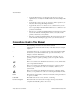
Chapter 4 BIOS This chapter contains information on BIOS, the low-level interface between the hardware and PC software that configures and tests your hardware at boot up. This BIOS (Basic Input Output System) provides an easy-to-use graphical user interface to allow you to configure system aspects according to your needs. Entering BIOS Setup To enter the BIOS setup program, perform the following steps. 1. Turn on or reboot the system. A screen appears with a series of diagnostic checks. 2.
Appendix A Specifications This appendix describes the environmental, electrical, and mechanical specifications of the VXIpc 800 Series embedded computer. Unless otherwise specified, these specifications apply to all models in the VXIpc 800 Series. Requirements Characteristic Specification VXIbus Configuration Space 64 B A24 or A32 Space 16 KB Minimum (Programmable) Electrical VXIpc-850 Current (A) Voltage (V) © National Instruments Corporation Typical Maximum (Fused) +5 5.82 A 12 A -5.
Appendix A Specifications VXIpc-860 Current (A) Voltage (V) Typical Maximum (Fused) +5 8.52 A 12 A -5.2 224.5 mA 2A -2 67.2 mA 2A +12 2.60 mA 2A -12 2.43 mA 2A Physical Characteristic VXIpc 800 Series User Manual Specification Size Two-slot VXIbus C-Size Module (233.35 by 340 by 60.96 mm) Board Dimensions Fully Enclosed, Shielded VXI C-Size Board 233.35 by 340 mm (9.187 by 13.386 in.
Appendix A Specifications Environmental Characteristic Note: Specification Temperature 0° to 55° C Operating; -20° to 70° C Storage Relative Humidity 0% to 95% Noncondensing, Operating; 0% to 95% Noncondensing, Storage EMI FCC Class A Verified, EC Verified Vibration Operational: 5 to 500 Hz, 0.31 g, 3 axes Non-operational: 5 to 500 Hz, 2.5 g, 3 axes Functional Shock MIL-T-28800E Class 3 (per Section 4.5.5.4.
Appendix A Specifications Capability Code VXIpc 800 Series User Manual Description BLT, MBLT (master) VMEbus master block and D64 transfers BLT, MBLT (slave) VMEbus slave block and D64 transfers RMW (master) VMEbus master read/modify/write transfers RMW (slave) VMEbus slave read/modify/write transfers RETRY (master) VMEbus master retry support RETRY (slave) VMEbus slave retry support FSD First slot detector SCON VMEbus System Controller (Automatic Detection) PRI, RRS Prioritized or Rou
Appendix A Specifications Adding RAM To add RAM to the VXIpc 800, remove the top cover and add SIMM modules to the empty SIMM sockets. National Instruments recommends the following types of SIMMs for use with the VXIpc-850 Series controller (Fast Page Mode): 8 MB: 2 MB x 36 SIMMs — 70 ns 16 MB: 4 MB x 36 SIMMs — 70 ns 32 MB: 8 MB x 36 SIMMs — 70 ns The VXIpc-860 can use Fast Page Mode (FPM), Extended Data Out (EDO), or Bursts Extended Data Out (BEDO).
Appendix VXIpc 800 Series System Resources B This appendix describes what system resources are available on the VXIpc 800 Series and where they are allocated. Because PCI is a relatively new addition to PCs, this appendix describes how PCI interrupts fit into a PC architecture before listing the devices that use them. PCI Interrupts PCI interrupts can be shared by multiple devices and are therefore more flexible than ISA interrupts.
Appendix B VXIpc 800 Series System Resources Table B-1. VXIpc 800 Series ISA Interrupt Resource Allocations (Continued) ISA Interrupt PCI Interrupt Device 5 INTC, INTB GPIB/PCMCIA Slot/Expansion 6 None Floppy Drive 7 None LPT1 8 None RTC 9 None Ethernet 10 INTA VXI, SCSI, PCMCIA 11 None GPIB/PCMCIA Slot/Expansion 12 None Mouse 13 None FPERR 14 INTD IDE 15 None PCMCIA Slot/Expansion Table B-2.
Appendix B VXIpc 800 Series System Resources Table B-3.
Appendix C LED Indicators This appendix describes how to read the LEDs on the front panel to interpret the status of the VXIpc 800 Series. VXIbus Interface Status LEDs The VXIbus interface status LEDs are located at the top of the module and include four LEDs: FAILED, SYSFAIL, ONLINE, and TEST. They indicate the various stages of initialization that occur as the VXIpc 800 boots. The following paragraphs describe each LED. SYSFAIL LED The SYSFAIL LED is lit when the VMEbus SYSFAIL signal is asserted.
Appendix C LED Indicators LEDs and System Startup Cycle Table C-1 shows a system startup cycle and possible points of failure, up to and including the state in which the VXIinit initialization program asserts the ONLINE LED. Table C-1. LEDs and System Startup Status Step LEDs Lit Possible Problem if VXIpc 800 Fails Status 1 None Machine just turned on. The VXIpc 800 is not receiving power. 2 FAILED, SYSFAIL Now asserting SYSFAIL because VXIbus interface has not been initialized yet.
Appendix C LED Indicators If either the SYSFAIL or FAILED LED remains lit, perform the following steps. 1. Power off the mainframe. 2. Remove all other modules from the mainframe. 3. Make sure that the VXIpc 800 jumper settings are correct. 4. Make sure that the VXIpc 800 is seated properly in the mainframe. 5. Power on the mainframe and observe whether the SYSFAIL and FAILED LEDs become unlit some time before the operating system boots.
Appendix C LED Indicators LINK LED The LINK LED indicates LINK status and can generally be used to check if Ethernet activity is occurring. DSEL LED The DSEL (Device Select) LED lights when Ethernet registers are being accessed.
Appendix Front Panel and Connectors D This appendix describes the front panel and connectors on the VXIpc 800 Series. This material contains the information relevant to VXIplug&play Specification VPP-8, VXI Module/Mainframe to Receiver Interconnection. Note: The illustrations in this appendix show the mating face of the connectors. An asterisk suffix (*) on a signal name indicates that the signal is active low.
Appendix D Front Panel and Connectors Front Panel Figure D-1 shows the front panel layout of the VXIpc-800. The drawing shows dimensions relevant to key elements on the front panel. Dimensions are shown in inches and millimeters, with millimeter dimensions in square brackets. The front panel thickness for all models in the VXIpc 800 Series is 2.49 mm (0.098 in.). SYSF FAILED ONLINE TEST DRIVE ACC TX RX DSEL LNK 1 2 G P I B TRG IN TRG OUT CLK RESET VXIpc-850 TM Figure D-1.
Appendix D Front Panel and Connectors Keyboard and Mouse Figure D-2 shows the location and pinouts for the keyboard and mouse connectors on the VXIpc 800 Series. Table D-1 gives the name and description for the keyboard and mouse connector signals. Amp manufactures a mating connector with part numbers 212437-4 (housing), 212435-7 (ferrule), and 66735-4 (pin contact). 4 6 2 Keyboard 1 3 5 4 6 1 2 2 Mouse 1 3 5 Figure D-2. Keyboard and Mouse Connectors Location and Pinout Table D-1.
Appendix D Front Panel and Connectors VGA Figure D-3 shows the location and pinouts for the VGA connector on the VXIpc 800 Series. Table D-2 gives the name and description for the VGA connector signals. Amp manufactures a mating connector with part numbers 748364-1 (housing) and 748333-2 (pin contact). 15 10 5 VGA 11 6 1 1 2 Figure D-3. VGA Connector Location and Pinout Table D-2.
Appendix D Front Panel and Connectors Table D-2. VGA Connector Signals (Continued) Pin Signal Name Signal Description 9 +5 VDC +5 VDC 10 GND Ground 11 NC Not Connected 12 SD Serial Data 13 HSync Horizontal Sync 14 VSync Vertical Sync 15 SC Serial Clock Ethernet Figure D-4 shows the location and pinouts for the Ethernet connector on the VXIpc-800. Table D-3 gives the name and description for the Ethernet connector signals. Amp manufactures a mating connector, part number 554739-1.
Appendix D Front Panel and Connectors Table D-3. Ethernet Connector Signals Pin Signal Description 1 Differential Transmit 2 Differential Transmit 3 Differential Receive 4 NC 5 NC 6 Differential Receive 7 NC 8 NC COM1 and COM2 Figure D-5 shows the location and pinouts for the COM1 and COM2 connectors on the VXIpc 800. Table D-4 gives the name and description for the COM1 and COM2 connector signals.
Appendix D 6 Front Panel and Connectors 1 COM1 9 5 6 1 1 2 COM2 9 5 Figure D-5. COM1 and COM2 Connectors Location and Pinout Table D-4.
Appendix D Front Panel and Connectors Parallel Port Figure D-6 shows the location and pinouts for the IEEE-1284 connector on the VXIpc-800. Table D-5 gives the name and description for the IEEE-1284 connector signals. Amp manufactures a parallel port compatible connector, part number 2-175677-5. SYSF FAILED ONLINE TEST DRIVE ACC 1 2 36 18 Parallel Port 19 1 Figure D-6.
Appendix D Front Panel and Connectors Table D-5.
Appendix D Front Panel and Connectors SCSI Figure D-7 shows the location and pinouts for the SCSI connector on the VXIpc-800. Table D-6 gives the name and description for the SCSI connector signals. Amp manufactures a SCSI compatible connector, part number 749111-4. 36 18 1 2 SCSI 19 1 Figure D-7.
Appendix D Front Panel and Connectors Table D-6.
Appendix D Front Panel and Connectors GPIB (IEEE-488.2) Figure D-8 shows the location and pinouts for the GPIB connector on the VXIpc-800. Table D-7 gives the name and description for the GPIB connector signals. ITT Cannon manufactures a GPIB mating connector, part number MDSM-255C-Z11. 1 2 14 1 GPIB 25 13 Figure D-8.
Appendix D Front Panel and Connectors Table D-7.
Appendix D Front Panel and Connectors External SMBs Figure D-9 shows the location and pinouts for the SMB connectors on the VXIpc 800. The SMB connectors are used for an external clock signal and TTL trigger input and output. Table D-8 gives the name and description for the SMB connector signals. Also see Table D-9 for a description of the signal characteristics for the SMB connections. Amp manufactures an SMB mating connector, part number 1-413985-0. 1 2 Center Shield SMB Figure D-9.
Appendix D Front Panel and Connectors Speaker Figure D-10 shows the location of the speaker connection on the VXIpc-800. Switchcraft manufactures a mating speaker connector, part number 750. 1 2 Speaker Figure D-10.
Appendix D Front Panel and Connectors Signal Characteristics Refer to the relevant standard for the signal characteristics for VGA, SCSI, Ethernet, keyboard, mouse, parallel, serial, and GPIB. Table D-9 shows the signal characteristics for the SMB and speaker connections. Table D-9. Signal Characteristics for SMB and Speaker Connections Signal Voltage Range Maximum Current Frequency Range SMB (TRIG out, CLK out) 0 to 3.4 V 200 mA DC-10 MHz Speaker 0 to 4.
Appendix D Front Panel and Connectors VXIbus P1 and P2 Figure D-11 shows the location and pinouts for the VXIbus connector on the VXIpc 800 Series. Table D-10 gives the name and description for the VXIbus P2 connector signals. Table D-11 gives the name and description for the VXIbus P1 connector signals. P2 Connector C32 B32 A32 C1 B1 A1 P1 Connector Figure D-11. VXIbus Connectors Location and Pinout Table D-10.
Appendix D Front Panel and Connectors Table D-10. VXIbus P2 Connector Signals (Continued) Pin VXIpc 800 Series User Manual Row C Row B Row A 13 –2 V +5 V –5.2 V 14 Not Connected D16 MODID06 15 Not Connected D17 MODID05 16 GND D18 GND 17 Not Connected D19 MODID04 18 Not Connected D20 MODID03 19 –5.2 V D21 -5.
Appendix D Front Panel and Connectors Table D-11.
Appendix D Front Panel and Connectors Table D-11.
Appendix Modifying and Installing I/O Expansion Boards E This appendix explains how to modify and install an I/O board in the VXIpc 800 Series. Notice that some material is different between the VXIpc-850 and the VXIpc-860. Height of VXIpc-850 Plug-In Boards In general, the VXIpc-850 can accommodate any standard-size PCI card and any XT-height ISA card. The height of an I/O card is measured from the bottom of the bus connector to the top of the board, as shown in Figure E-1. Height (4.2 in.
Appendix E Modifying and Installing I/O Expansion Boards Length of VXIpc-850 Plug-In Boards The VXIpc-850 will accommodate PCI or ISA I/O boards that are up to 4.2 in. high and up to 13.415 in. long when DRAM SIMMs 0.85 in. or shorter are used on the processor board (National Instruments provides 0.85 in. SIMMs). Due to slight variances in I/O board geometries, however, take care in every application to identify possible contact with the SIMMs. The maximum recommended board length is 7.72 in.
Appendix E Modifying and Installing I/O Expansion Boards Length of ISA Plug-In Boards Because ISA boards mount with the components facing away from the CPU card, which contains the processor and system RAM, tall DRAM SIMMs may interfere with the circuit card of the plug-in board. Most SIMM modules are at least 1 in. high and would extend into the ISA circuit card keepout area. Therefore, National Instruments provides SIMMs of 0.85 in. high, and does not recommend the use of cards that are longer than 7.
Appendix E Modifying and Installing I/O Expansion Boards Height of VXIpc-860 Plug-In Boards In general, the VXIpc-860 can accommodate any standard-size PCI card and any XT-height ISA card. The height of an I/O card is measured from the bottom of the bus connector to the top of the board, as shown in Figure E-4. .48 in. Component Height (PCI Component Side) .07 in. Component Height (ISA Solder Side) With .85 in. Tall SIMMs 2.51 in. Height (4.2 in. max) 1.50 in. 4.36 in. Length (8.4 in.
Appendix E Modifying and Installing I/O Expansion Boards Length of VXIpc-860 Plug-In Boards The VXIpc-860 can accommodate PCI or ISA I/O boards that are up to 4.2 in. high and up to 8.4 in. long. When DRAM SIMMs 0.85 in. are used on the processor board, the component-side component height on a PCI I/O board shall be 0.48 in. tall in the area shown in Figure E-4. For the same height DRAM SIMMs, the ISA I/O board solder-side component height shall be 0.07 in. tall in the area shown in Figure E-4.
Appendix E Modifying and Installing I/O Expansion Boards Length of ISA Plug-In Boards Because ISA boards mount with the components facing away from the CPU card, which contains the processor and system RAM, tall DRAM SIMMs may interfere with the circuit card of the plug-in board. Most SIMM modules are at least 1 in. high and would extend into the ISA circuit card. Therefore, National Instruments provides SIMMs of 0.85 in. high to give a clearance of 0.07 in.
Appendix E Modifying and Installing I/O Expansion Boards Installing an I/O Board The following material applies equally to all models in the VXIpc 800 Series. Materials Needed You need the following pieces to install an expansion board in the VXIpc-800: • A user-defined panel is required on the expansion boards based on National Instruments blank PCI or ISA panels. The panel should be manufactured from 0.03 in. (0.76 mm) thick 1010 cold rolled steel. The finish should be 0.0003 in. (0.
Appendix E Modifying and Installing I/O Expansion Boards with a lock washer (hole diameter should be 0.125 in.). In either case, use a 4-40 x 1/4 in. stainless steel panhead screw to mount the board/bracket assembly to the front panel. a. PCI Board Installed b. ISA Board Installed Figure E-7. PCI Board and ISA Board Installed in a VXIpc-800 Figures E-8 and E-9 give dimensions and instructions for creating a connector cutout and expansion bracket for a PCI board.
Appendix E Modifying and Installing I/O Expansion Boards .475 [12.07] (I/O Connector Window) (.200 [5.08]) 1 I/O Connector Window, (.475 [12.07] X 3.224 [81.89]) 3.464 [87.99] 4.46 [113.28] 4.080 [103.63] .09 [2.3] .240 [6.10] .19 [4.8] .180 [4.57] .560 [14.22] .760 [19.30] 1 1 Install PEM self-clinching nut, P/N CLS-440-0, per manufacturer's specifications, far side, or drill through ø.125 [3.18] for 4-40 screw and nut. Figure E-9.
Appendix E Modifying and Installing I/O Expansion Boards Figures E-10 and E-11 give dimensions and instructions for creating a connector cutout and expansion bracket for an ISA board. ISA Expansion Bracket 3.500 [88.90] (I/O Connector Window) 4.200 [106.68] (XT Card) .300 [7.62] (.050 [1.27]) 1 1 Length of XT ISA card shall be 7.72 [196.1] if SIMMs on processor card are taller than .85 [21.6]. Otherwise ISA specification length of 13.415 [340.74] may be used. Figure E-10.
Appendix E Modifying and Installing I/O Expansion Boards .490 [12.45] (I/O Connector Window) (.200 [5.08]) I/O Connector Window, (490 [12.45] X 3.500 [88.90]) 3.550 [90.17] 4.46 [113.28] 4.080 [103.63] .09 [2.3] .050 [1.27] .19 [4.8] .180 [4.57] .560 [14.22] .760 [19.30] 1 1 Install PEM self-clinching nut, P/N CLS-440-0, per manufacturer's specifications, far side, or drill through ø.125 [3.18] for 4-40 screw and nut. Figure E-11.
Appendix F Common Questions This appendix answers common questions you may have when using the VXIpc 800 Series. What do the LEDs on the front of the VXIpc 800 mean? Refer to Appendix C, LED Indicators, for a description of the front panel LEDs. Is something wrong with the VXIpc 800 if the red SYSFAIL and FAILED LEDs stay lit after booting the VXIpc 800? If either the SYSFAIL or FAILED LED remains lit, refer to Appendix C, LED Indicators, for troubleshooting steps.
Appendix F Common Questions If I boot the computer without video, and then plug in the video, why is it in black and white? When the computer first boots, the video chips try to synchronize with the monitor. If the monitor is not there, the video chips cannot synchronize and establish color. You need to have the monitor attached at boot time to get color. I’ve installed the SCSI software.
Appendix F Common Questions What if my keyboard connector does not fit into the keyboard port on the VXIpc 800? You can plug keyboards that have a 6-pin Mini DIN PS/2 type connector directly into the VXIpc 800. You can use the keyboard adapter cable that is included with every VXIpc 800 kit to adapt the larger AT keyboard connector to the 6-pin Mini DIN connector.
Appendix F Common Questions How do I check the configuration of the memory, floppy drive, hard drive, time/date, and so on? You can view these parameters in the BIOS setup. To enter the BIOS setup, reboot the VXIpc 800 and press the key during the memory tests. Refer to Chapter 4, BIOS, for more information. Can I upgrade my VXIpc 800? You can upgrade the modular CPU card to upgrade the processor. Contact National Instruments for information.
Appendix Customer Communication G For your convenience, this appendix contains forms to help you gather the information necessary to help us solve your technical problems and a form you can use to comment on the product documentation. When you contact us, we need the information on the Technical Support Form and the configuration form, if your manual contains one, about your system configuration to answer your questions as quickly as possible.
Fax-on-Demand Support Fax-on-Demand is a 24-hour information retrieval system containing a library of documents on a wide range of technical information. You can access Fax-on-Demand from a touch-tone telephone at (512) 418-1111. E-Mail Support (currently U.S. only) You can submit technical support questions to the applications engineering team through e-mail at the Internet address listed below. Remember to include your name, address, and phone number so we can contact you with solutions and suggestions.
Technical Support Form Photocopy this form and update it each time you make changes to your software or hardware, and use the completed copy of this form as a reference for your current configuration. Completing this form accurately before contacting National Instruments for technical support helps our applications engineers answer your questions more efficiently.
Hardware and Software Configuration Form Record the settings and revisions of your hardware and software on the line to the right of each item. Complete a new copy of this form each time you revise your software or hardware configuration, and use this form as a reference for your current configuration. Completing this form accurately before contacting National Instruments for technical support helps our applications engineers answer your questions more efficiently.
Other Products Mainframe make and model ________________________________________________________ Microprocessor __________________________________________________________________ Clock frequency or speed ___________________________________________________________ Type of video board installed _______________________________________________________ Operating system and version _______________________________________________________ Operating system mode _______________________________________________________
Documentation Comment Form National Instruments encourages you to comment on the documentation supplied with our products. This information helps us provide quality products to meet your needs. Title: VXIpc™ 800 Series User Manual Edition Date: September 1997 Part Number: 321744A-01 Please comment on the completeness, clarity, and organization of the manual.
Glossary Prefix Meaning Value n- nano- 10–9 µ- micro- 10–6 m- milli- 10–3 k- kilo- 103 M- mega- 106 G- giga- 109 A A Amperes address Character code that identifies a specific location (or series of locations) in memory address space A set of 2 memory locations differentiated from other such sets in VXI/ VMEbus systems by six addressing lines known as address modifiers. n is the number of address lines required to uniquely specify a byte location in a given space.
Glossary B b bits B bytes backplane An assembly, typically a printed circuit board, with 96-pin connectors and signal paths that bus the connector pins. A C-size VXIbus system will have two sets of bused connectors called J1 and J2. A D-size VXIbus system will have three sets of bused connectors called J1, J2, and J3. BERR* Bus error signal BIOS Basic Input/Output System. BIOS functions are the fundamental level of any PC or compatible computer.
Glossary DRAM Dynamic RAM (Random Access Memory); storage that the computer must refresh at frequent intervals E ECL Emitter-Coupled Logic EDO Extended Data Out; a DRAM architecture that shortens overall access latency, improving performance EEPROM Electronically Erasable Programmable Read Only Memory embedded controller An intelligent CPU (controller) interface plugged directly into the VXI backplane, giving it direct access to the VXIbus.
Glossary I IDE Integrated Drive Electronics. Denotes the most common interface to the hard drive on PCs. IEEE Institute of Electrical and Electronics Engineers in.
Glossary L LED Light-emitting diode M m meters master A functional part of a VME/VXIbus device that initiates data transfers on the backplane. A transfer can be either a read or a write. MB megabytes of memory MITE A National Instruments custom ASIC, a sophisticated dual-channel DMA controller that incorporates the Synchronous MXI and VME64 protocols to achieve high-performance block transfer rates MODID Module ID Lines.
Glossary P PCI Peripheral Component Interconnect. The PCI bus is a high-performance 32-bit or 64-bit bus with multiplexed address and data lines. PCMCIA Personal Computer Memory Card International Association PEM Penn Engineering Manufacturing Corporation. A manufacturer of nuts pressed into metal POSC Power-On Self Configuration.
Glossary T trigger Either TTL or ECL lines used for intermodule communication TTL Transistor-Transistor Logic V V Volts VISA Virtual Instrument Software Architecture. This is the general name given to VISA and its associated architecture. VME Versa Module Eurocard or IEEE 1014 VMEbus System Controller A device configured for installation in Slot 0 of a VXIbus mainframe or Slot 1 of a VMEbus chassis.
Index A ACCESS LED, 1-7, C-3 address map, I/O (table), B-3 to B-4 application-specific interface chips, custom, 1-5 audio capability. See speaker. B BIOS. See also CMOS.
Index SCSI, D-10 to D-11 signal characteristics, D-16 speaker, D-15 VGA, D-4 to D-5 VXIbus P1 and P2, D-17 to D-20 CPU card, 2-4 custom application-specific interface chips, 1-5 customer communication, xii, G-1 to G-2 environmental specifications, A-3 equipment, optional, 1-3 Ethernet connector and signals, D-5 to D-6 LEDs for status, 1-7, C-3 to C-4 overview, 2-3 power-on defaults, PC configuration VXIpc 800 Series, 3-13 expansion boards. See I/O expansion boards.
Index I J IDE controller overview, E-3 problems with booting hard disk, F-4 using internal IDE drive and external SCSI hard drive, F-4 installation. See also configuration.
Index O S ONLINE LED, 1-6, C-1 SCSI interface common questions and answers, F-2, F-4 connector and signals, D-10 to D-11 overview, 2-4 setting up in BIOS, F-2 termination, PC configuration, 3-11 serial port connectors and signals, D-6 to D-7 signals COM1 and COM2 connectors (table), D-7 Ethernet connector (table), D-6 GPIB (IEEE 488.
Index V speaker connecting external speaker to VXIpc 800 Series, F-3 connector location (figure), D-15 signal characteristics (table), D-16 specifications adding RAM, A-5 electrical, A-1 to A-2 environmental, A-3 physical, A-2 requirements, A-1 VMEbus capability codes, A-3 to A-4 switch settings, 3-3. See also configuration.