
Bridge User Manual


Chapter 11 Loops and Charts
BridgeVIEW User Manual 11-6 © National Instruments Corporation
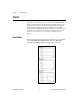
8. Rescale the knob. Using the Labeling tool, double-click on
10.0
in the
scale around the knob, and replace it with
2.0
.
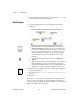
Block Diagram
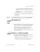
9. Open the block diagram and create the diagram in the following
illustration.
a. Place the While Loop in the block diagram by selecting it from
Functions»Structures. The While Loop is a resizable box that is
not dropped on the diagram immediately. Instead, you have the
chance to position and resize it. To do so, click in an area above
and to the left of all the terminals. Continue holding down the
mouse button and drag out a rectangle that encompasses the
terminals.
b. Select the Random Number (0–1) function from Functions»
Numeric.
c. Wire the diagram as shown in the Block Diagram, connecting the
Random Number (0–1) function to the Random Signal chart
terminal, and the Enable switch to the conditional terminal of the
While Loop. Leave the Loop Delay terminal unwired for now.
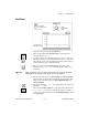
10. Return to the front panel and turn on the vertical switch by clicking on
it with the Operating tool.
11. Save the VI as
Random Signal.vi
in the
BridgeVIEW\Activity
directory.
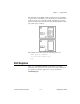
12. Run the VI.
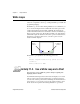
The While Loop is an indefinite looping structure. The diagram within it
executes as long as the specified condition is TRUE. In this example, as
long as the switch is on (TRUE), the diagram continues to generate random
numbers and display them on the chart.