
User's Manual

NI 4070/4072 Calibration Procedure 30 ni.com
57. Call niDMM_Read. Subtract the previously calculated 100 Ω range
offset from this measurement. Verify that the result falls between the
tolerances listed in Table 18.
You have completed verifying the 2-wire resistance of the NI 4070/4072.
Select one of the following options:
• If you want to continue verifying other modes, go to the Verifying DC
Current section.
• If you do not want to verify other modes and you are performing a
post-adjustment verification, go to the Completing the Adjustment
Procedures section.
• If you do not want to verify any additional modes and you are
performing a pre-adjustment verification, call
niDMM_close to close
the session.
Verifying DC Current
To verify the DC current of the NI 4070/4072, complete the following steps:
1. Reset the calibrator.
2. Fasten the connectors on one end of the Fluke 5440 cable to the
NI 4070/4072 HI SENSE and LO banana plug connectors, and connect
the connectors on the other end of the cable to the HI and LO calibrator
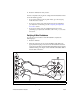
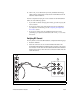
binding posts. Figure 3 shows the correct connections. Table 9 lists the
cable connections.
Figure 3. Cable Connections for Current
1 NI 4070/4072 2 Fluke 5700A/5720A Calibrator 3 Fluke 5440 Cable
HI
LO
300V
MAX
HI
LO
AUX
I/O
1A, 250V
MAX
300V
MAX
5V
MAX
AMPS
INPUT
SENSE
W 4W
6½-Digit FlexDMM
CAT II
V
W
HI
LO
HI
LO
HI
SENSE
VΩ
OUTPUT
VΩA
AUX
CURRENT
GUARD GROUND
1
2
3