
User's Manual
© National Instruments Corporation 9 NI 4070/4072 Calibration Procedure
12. Set the input resistance of the NI 4070/4072 to 10 MΩ by calling
niDMM_SetAttributeViReal64 with the following parameters:
• Attribute_ID =
NIDMM_ATTR_INPUT_RESISTANCE
• Attribute_Value = NIDMM_VAL_10_MEGAOHM
13. Call
niDMM_Read. Verify that this measurement falls between the
limits listed in Table 15.
14. Call
niDMM_ConfigureMeasurement with the following
parameters:
• Function =
NIDMM_VAL_DC_VOLTS
• Range = 100
• Resolution = 100e–6
15. Set the input resistance of the NI 4070/4072 to 10 MΩ by calling
niDMM_SetAttributeViReal64 with the following parameters:
• Attribute_ID =
NIDMM_ATTR_INPUT_RESISTANCE
• Attribute_Value = NIDMM_VAL_10_MEGAOHM
16. Call
niDMM_Read. Verify that this measurement falls between the
limits listed in Table 15.
17. Call
niDMM_ConfigureMeasurement with the following
parameters:
• Function =
NIDMM_VAL_DC_VOLTS
• Range = 300
• Resolution = 300e–6
18. Set the input resistance of the NI 4070/4072 to 10 MΩ by calling
niDMM_SetAttributeViReal64 with the following parameters:
• Attribute_ID =
NIDMM_ATTR_INPUT_RESISTANCE
• Attribute_Value = NIDMM_VAL_10_MEGAOHM
19. Call
niDMM_Read. Verify that this measurement falls between the
limits listed in Table 15.
20. Remove the shorting bar from the NI 4070/4072.
21. Reset the calibrator.
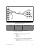
22. Fasten the connectors on one end of the Fluke 5440 cable to the
appropriate banana plug connectors of the NI 4070/4072, and fasten
the connectors on the other end of the cable to the appropriate
calibrator binding posts. Figure 1 shows the correct connections.
Table 1 lists the cable connections.