USER GUIDE AND SPECIFICATIONS NI USB-9421 8-Channel, 24 V Logic, Sinking Digital Input Device This user guide describes how to use the National Instruments USB-9421 and lists the device specifications. In this user guide, the NI USB-9421 with screw terminal and the NI USB-9421 with D-SUB are referred to inclusively as the NI USB-9421. Introduction The NI USB-9421 data acquisition device provides a USB interface with connections for eight digital input channels.
Dimensions Figures 2 and 3 show the NI USB-9421 device dimensions. Hi-Speed USB Carrier NI USB-9162 140.23 mm (5.521 in.) 120.68 mm (4.751 in.) 137.82 mm (5.426 in.) 118.26 mm (4.656 in.) 88.12 mm (3.469 in.) 25.34 mm (0.998 in.) Figure 2. NI USB-9421 (Screw Terminal) Device in Millimeters (Inches) Hi-Speed USB Carrier NI USB-9162 125.76 mm (4.951 in.) 120.68 mm (4.751 in.) 123.38 mm (4.857 in.) 118.26 mm (4.656 in.) 88.12 mm (3.469 in.) 25.34 mm (0.998 in.) Figure 3.
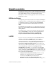
Safety Guidelines Operate the NI USB-9421 only as described in these operating instructions. Although the NI 9421 module may have more stringent certification standards than the NI USB-9421, when used with the NI USB-9162 carrier, the combined system may be limited. Refer to the Specifications section for more details. Note Hot Surface This icon denotes that the component may be hot. Touching this component may result in bodily injury.
Related Documentation Each application software package and driver includes information about writing applications for taking measurements and controlling measurement devices. The following references to documents assume you have NI-DAQmx 8.7 or later, and where applicable, version 7.1 or later of the NI application software.
• Taking Measurements—Contains the conceptual and how-to information you need to acquire and analyze measurement data in LabVIEW, including common measurements, measurement fundamentals, NI-DAQmx key concepts, and device considerations. LabWindows/CVI The Data Acquisition book of the LabWindows/CVI Help contains measurement concepts for NI-DAQmx.
ANSI C without NI Application Software The NI-DAQmx Help contains API overviews and general information about measurement concepts. Select Start»All Programs»National Instruments»NI-DAQ»NI-DAQmx Help. The NI-DAQmx C Reference Help describes the NI-DAQmx Library functions, which you can use with National Instruments data acquisition devices to develop instrumentation, acquisition, and control applications. Select Start»All Programs»National Instruments»NI-DAQ» NI-DAQmx C Reference Help. .
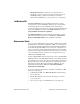
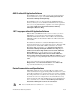
Training Courses If you need more help getting started developing an application with NI products, NI offers training courses. To enroll in a course or obtain a detailed course outline, refer to ni.com/training. Technical Support on the Web For additional support, refer to ni.com/support or zone.ni.com. Installing the Software Software support for the NI USB-9421 for Windows Vista/XP/2000 is provided by NI-DAQmx. The DAQ Getting Started Guide, which you can download at ni.
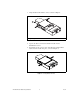
3. Align the I/O module with the carrier, as shown in Figure 4. 1 1 High Voltage Screw Terminal Backshell Figure 4. Module Installation 4. Squeeze the latches and insert the NI 9421 module into the NI USB-9162 carrier. 5. Press firmly on the connector side of the NI 9421 module until the latches lock the module into place, as shown in Figure 5. Figure 5. Locking Module into Place NI USB-9421 User Guide and Specifications 8 ni.
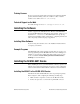
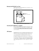
Mounting the NI USB-9421 to a Panel Threaded inserts are located in the NI USB-9421 for mounting it to a panel. Refer to Figure 6 for dimensions. 85.7 mm (3.37 in.) 72.2 mm (2.84 in.) Threaded Insert M3 x 0.5 8.5 mm (0.34 in.) Max Depth 76.1 mm (3.00 in.) Figure 6. Module Dimensions in Millimeters (Inches) Connecting the NI USB-9421 to a Computer Plug one end of the USB cable into the NI USB-9421 and the other end into an available USB port on the computer.
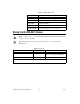
Table 1. LED State/Device Status LED State Device Status Not lit Device not connected or in suspend. On, not blinking Device connected, but no module installed. Single-blink Operating normally. Double-blink Operating normally. Quadruple-blink Device error. Refer to ni.com/support. Wiring the NI USB-9421 Device A high voltage screw terminal backshell must be installed when using hazardous voltages (>42.4 Vpk, 60 VDC). Caution Note Table 2 illustrates the accessories available from ni.
Each channel of the NI USB-9421 has a terminal or pin, DI, to which you can connect voltage or current signals. The NI USB-9421 also has a common terminal or pin, COM, that is internally connected to the isolated reference of the module. Each digital input channel on the NI USB-9421 has an LED that indicates the state of that channel. Refer to Table 3 for the terminal assignments of the NI USB-9421 with screw terminal. Refer to Figure 7 for the pin assignments of the NI USB-9421 with D-SUB. Table 3.
DI0 NC DI1 DI2 NC DI3 DI4 NC DI5 DI6 NC DI7 0 3 4 7 14 15 16 17 18 19 20 21 22 23 24 25 1 2 3 4 5 6 7 8 9 10 11 12 13 COM NC COM COM NC COM COM NC COM COM NC COM COM Figure 7. Pin Assignments Connecting Devices to the NI USB-9421 The NI USB-9421 has sinking inputs, meaning that when current goes through or voltage is applied to the DI terminal or pin, DI provides a path to ground for the current or voltage. The NI USB-9421 internally limits current signals connected to DI.
Sourcing-Output Device DI External + Power _ Supply COM NI USB-9421 Figure 8. Connecting a Device to the NI USB-9421 (3-Wire Device Shown) The NI USB-9421 channel registers as ON when the sourcing-output device applies a voltage or drives a current to DI that is in the input ON range. The channel registers as OFF when the device applies a voltage or drives a current to DI that is in the input OFF range. If no device is connected to DI, the channel registers as OFF.
Figure 10. Assembled High Voltage Screw Terminal Backshell Specifications The following specifications are typical for the range 0 to 60 °C unless otherwise noted. All voltages are relative to COM unless otherwise noted. Input Characteristics Number of channels................................8 Input type ................................................Sinking Digital logic levels OFF state Input voltage.............................≤5 V Input current .............................
Bus Interface USB specification .................................. USB 2.0 Hi-Speed Physical Characteristics Dimensions With screw terminal........................ 14.0 cm × 8.8 cm × 2.5 cm (5.52 in. × 3.47 in. × 1.00 in.) With 25-pin D-SUB ........................ 12.6 cm × 8.8 cm × 2.5 cm (4.95 in. × 3.47 in. × 1.00 in.) Screw-terminal wiring............................ 12 to 24 AWG copper conductor wire with 10 mm (0.39 in.) of insulation stripped from the end Torque for screw terminals ................
NI USB-9421 with D-SUB Safety Voltages Channel-to-COM ....................................30 V max Isolation Channel-to-channel..........................No isolation between channels Channel-to-earth ground Withstand .................................1,000 Vrms, verified by a 5 second dielectric withstand test Continuous ...............................
Operating humidity (IEC 60068-2-56) ................................... 10 to 90% RH, noncondensing Storage humidity (IEC 60068-2-56) ................................... 5 to 95% RH, noncondensing Maximum altitude .................................. 2,000 m Pollution Degree (IEC 60664) ...............
Waste Electrical and Electronic Equipment (WEEE) At the end of their life cycle, all products must be sent to a WEEE recycling center. For more information about WEEE recycling centers and National Instruments WEEE initiatives, visit ni.com/environment/weee.htm. EU Customers ⬉ᄤֵᙃѻક∵ᶧࠊㅵ⧚ࡲ⊩ ˄Ё RoHS˅ Ёᅶ᠋ National Instruments ヺড়Ё⬉ᄤֵᙃѻકЁ䰤ࠊՓ⫼ᶤѯ᳝ᆇ⠽䋼ᣛҸ (RoHS)DŽ ݇Ѣ National Instruments Ё RoHS ড়㾘ᗻֵᙃˈ䇋ⱏᔩ ni.com/environment/rohs_chinaDŽ (For information about China RoHS compliance, go to ni.